Supercharge Your Innovation With Domain-Expert AI Agents!

An Electronic Programmable Fuse Circuit Structure Using Current Programming

A technology of current programming and circuit structure, which is applied in information storage, static memory, instruments, etc., can solve the problems of inconvenient use, large fusing resistance, and affecting the accuracy and stability of fusing current, so as to save research and development costs, The effect of increased fuse resistance and stable and reliable programming current

Active Publication Date: 2020-08-25
SHANGHAI HUALI MICROELECTRONICS CORP
View PDF2 Cites 0 Cited by
  • Summary
  • Abstract
  • Description
  • Claims
  • Application Information

AI Technical Summary

Problems solved by technology

[0004] Although the traditional voltage programming EFUSE structure circuit diagram can fuse the EFUSE fuse resistance, due to the excessive current, the locally accumulated heat of the polysilicon electric fuse is very large, causing the polysilicon electric fuse to burst
If the polysilicon fuse has been programmed at this time, most of the metal silicides on the metal chain have not migrated, so the resistance after the fuse is small and the reliability is very low.
Lead to a part of low resistance state, causing a lot of inconvenience in actual use
[0005] Electromigration technology requires only a small current to program the fuse. After electromigration, the fuse resistance of EFUSE is very large, and the fuse resistance has little effect on time and temperature. The key factor for its stability and reliability is Provide accurate and stable fusing current, but process and environmental changes often affect the accuracy and stability of fusing current, resulting in poor stability and reliability of the electronic programmable fuse circuit structure

Method used


Image

  • An Electronic Programmable Fuse Circuit Structure Using Current Programming
  • An Electronic Programmable Fuse Circuit Structure Using Current Programming
  • An Electronic Programmable Fuse Circuit Structure Using Current Programming

Examples


Embodiment Construction

[0024] In order to make the object, technical solution and advantages of the present invention clearer, the specific implementation of the present invention will be further described in detail below in conjunction with specific examples and accompanying drawings.

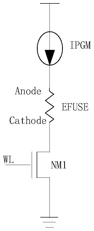
[0025] Such as figure 2 As shown, the fuse circuit structure using current programming includes fuse resistor EFUSE, programming transistor NM1, programming current source IPGM, the anode terminal Anode of the fuse resistor EFUSE is connected to the programming current source, and the cathode terminal Cathode of the fuse resistor EFUSE is connected to programming Transistor NM1, the other end of programming transistor NM1 is grounded, and the gate is connected to the word line signal WL at the same time. When the fuse resistor EFUSE performs the programming action, the programming current source IPGM applies the programming current to the anode terminal Anode of the fuse resistor EFUSE, and then the row decoding un...


PUM


Abstract

The invention discloses an electrically programming fuse circuit structure adopting current programming. The electrically programming fuse circuit structure adopting current programming comprises a matrix unit, a current mirror and a reference current source generation circuit; reference current generated by the reference current source generation circuit is proportionally amplified through the current mirror to form programming current; the programming current controls the matrix unit to perform fuse programming; the matrix unit comprises m*n fuse units, n column selection units and a decoding unit; the n column selection units are respectively connected with n columns of fuse units; each fuse unit comprises a fuse resistor and a programming transistor; each column selection unit comprises a column selection transistor; and the decoding unit is used for determining the position, where the fuse unit needing to perform fuse programming is. The invention provides the electrically programming fuse circuit structure adopting current programming; fuse programming is carried out by adoption of an electric migration mechanism; and the electrically programming fuse circuit structure adopting current programming has the excellent characteristics of being high in fusing resistance, and steady and reliable in programming fuse circuit structure.

Description

technical field [0001] The invention relates to the field of circuit protection, in particular to an electronic programmable fuse circuit structure using current programming. Background technique [0002] Electronically programmable fuse (EFUSE-electrically programming Fuse) technology is a technology developed according to the characteristics of polysilicon fuse. With the gradual maturity of the theory and technology of EFUSE, the scope of application of EFUSE expands rapidly. For example, multiple circuit modules with the same function are designed in the integrated circuit as a backup, and when one of the circuit modules is found to be defective, it is blown through the fuse unit and replaced by another circuit module with the same function. Another example is to design a general-purpose integrated circuit. According to the needs of different users, the unnecessary circuit modules are blown through the fuse unit, so that an integrated circuit design can be manufactured i...

Claims


Application Information

Patent Timeline
Patent Type & Authority Patents(China)
IPC IPC(8): G11C17/16G11C17/18
CPCG11C17/16G11C17/18
Inventor 任永旭金建明顾明
Owner SHANGHAI HUALI MICROELECTRONICS CORP
Features
  • R&D
  • Intellectual Property
  • Life Sciences
  • Materials
  • Tech Scout
  • Unparalleled Data Quality
  • Higher Quality Content
  • 60% Fewer Hallucinations
Learn More