
Tubular bus connection structure

A connection structure and tube busbar technology, applied in the direction of butt busbar connection, connection insulation, busbar installation, etc., to increase the current flow, reduce installation difficulty, and achieve the effect of electrical contact

Active Publication Date: 2017-10-24
GCA CO LTD
View PDF11 Cites 4 Cited by
  • Summary
  • Abstract
  • Description
  • Claims
  • Application Information

AI Technical Summary

Problems solved by technology

[0005] The technical problem to be solved by the present invention is to provide a pipe-busbar connection structure to meet the development needs of switchgear flow performance and miniaturization, and to upgrade the rated current without changing the existing switchgear

Method used

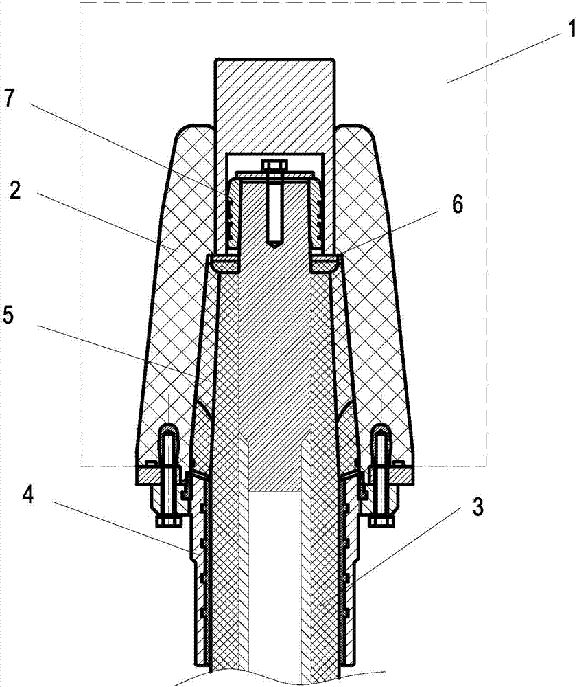
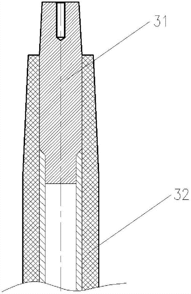
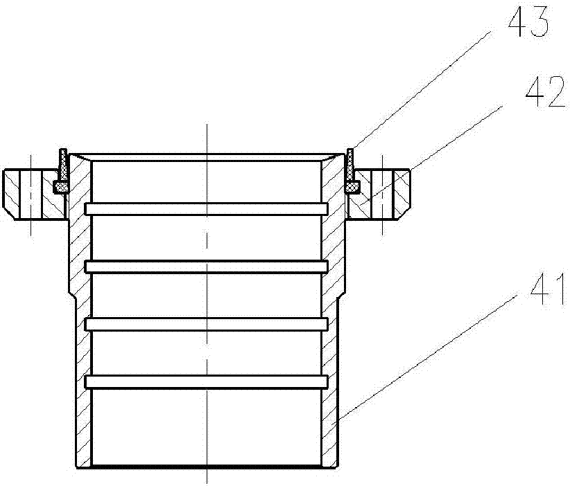

Image

  • Tubular bus connection structure
  • Tubular bus connection structure
  • Tubular bus connection structure

Examples


Embodiment 1

[0030] The purpose of the present invention is to solve the development needs of the current flow performance and miniaturization of the switchgear, and can upgrade the rated current without changing the existing switchgear; provide a reliable voltage resistance, strong flow capacity, and compact structure. , easy to install pipe bus connection structure.

[0031] In order to achieve the above purpose, if figure 1 As shown, the present invention is realized through the following technical solutions: a connection structure for pipe busbars, including a pipe busbar 3 , fasteners 4 , silicone rubber insulating parts 5 , stress support parts 6 and conductor connectors 7 . Among them, the entire pipe busbar connection structure is assembled into the socket 2 of the switch cabinet 1, and is electrically connected with the socket conductor in the socket 2 to realize the electrical conduction of the incoming and outgoing lines of the switch cabinet 1, so that the entire power system o...

Embodiment 2

[0038] The only difference between this embodiment and the first embodiment is that the stress support member 6 is not needed in this example, and other structures are the same as the first embodiment.


PUM


Abstract

The invention discloses a tubular bus connection structure, which is used for realizing electrical conduction of incoming and outgoing lines of a switch cabinet after being inserted into a socket of the switch cabinet. The tubular bus connection structure comprises a conductor connector, a tubular bus, a silicone rubber insulation member, a fastener and a strain supporting member, wherein the conductor connector is fixedly connected to the top part of the tubular bus, and is used for being inserted into the socket of the switch cabinet so as to be electrically connected with conductors of the socket; the silicone rubber insulation member sleeves the outer surface of a part between the portion (positioned below the conductor connector) of the tubular bus and the portion (positioned inside the switch cabinet) of the tubular bus when the tubular bus is in operation, and is used for carrying out insulation and electrical isolation on the socket of the switch cabinet; the fastener is mounted under the silicone rubber insulation member, and is used for being fixedly connected with the switch cabinet when in operation; and the strain supporting member comprises a metal force bearing ring and a semiconductive silicone rubber ring covering the metal force bearing ring. The tubular bus connection structure meets the development requirements for the through-flow performance and miniaturization of the switch cabinet, and can upgrade the rated current without changing the existing switching equipment.

Description

technical field [0001] The invention relates to the technical field of power transmission equipment for power cables, in particular to a connection structure of pipe busbars. Background technique [0002] In the power system, the incoming and outgoing lines of the inflatable cabinet are mostly connected by power cables and their accessories. The power cables have many years of experience in use and operation, and the insulation level is high, stable and reliable. However, the current capacity of the cable is relatively poor. Taking the 35kV power cable as an example, the maximum cross-section currently used is 630mm 2 , the rated current can only reach 1250A, which greatly restricts the development needs of the switchgear and cannot meet the requirements of many projects; in order to achieve the purpose of high current transmission of 2500A and above, two or more cables are generally used in parallel, requiring more The coordination of cables and their accessories will incr...

Claims


Application Information

Patent Timeline
Patent Type & Authority Applications(China)
IPC IPC(8): H02G5/00H01R4/70H01R4/56
CPCH01R4/56H01R4/70H02G5/007
Inventor 陈朝晖王萍萍邓广桓吕玉春
Owner GCA CO LTD
Learn More