A transmission line deicing device

A technology of transmission lines and longitudinal beams, which is applied in the installation of cables, overhead installations, electrical components, etc., and can solve problems such as broken wires, accidental injuries, and grounding short circuits, so as to avoid excessive bending, ensure safety, and avoid being damaged. damage effect

Active Publication Date: 2018-10-12
JINAN CITY CHANGQING DISTRICT POWER SUPPLY CO OF STATE GRID SHANDONG ELECTRIC POWER CO +1
View PDF4 Cites 0 Cited by
  • Summary
  • Abstract
  • Description
  • Claims
  • Application Information

AI Technical Summary

Problems solved by technology

Severe icing will cause grounding short circuit, disconnection, and even tower collapse accidents, which are extremely harmful
The traditional deicing methods are mainly manual operations, such as beating with bamboo poles, wooden sticks, ice picks, etc. These methods are not only difficult, time-consuming and laborious to deicing, but also the falling snow or ice can easily injure the staff and cause accidents harm
[0003] In response to this problem, people have invented deicing robots, but most of the deicing robots use ice knives or set sharp objects on the rollers to crush the ice. Although this method can remove the ice on the surface of the power line, it cannot There is also the danger of destroying the insulation layer on the surface of the transmission line, and the damage to the insulation layer on the surface of the transmission line at one end will bring more serious consequences

Method used


Image

  • A transmission line deicing device
  • A transmission line deicing device
  • A transmission line deicing device

Examples


Embodiment Construction

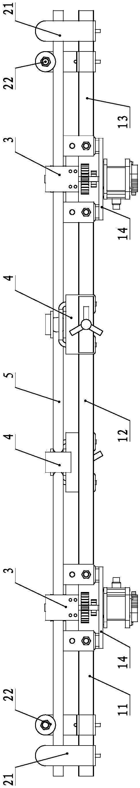
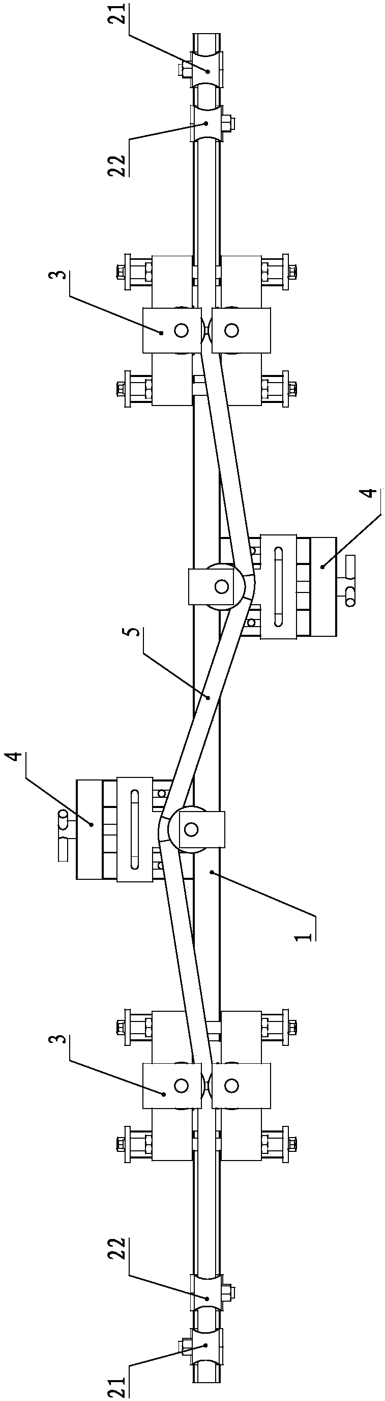
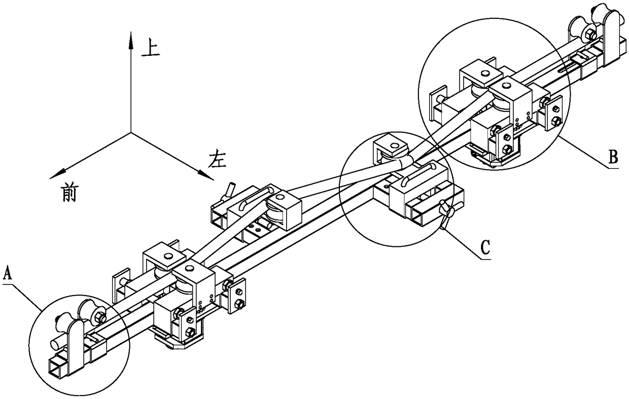
[0042] For the convenience of description, the coordinate system is defined as figure 1 , and the front and back directions are vertical, the left and right directions are horizontal, and the up and down directions are vertical.

[0043] Such as figure 1 , figure 2 with Figure 7 As shown, a five-way deicing device for a power transmission line includes a main frame body 1 , and the main frame body 1 includes a first longitudinal beam 11 , a second longitudinal beam 12 and a third longitudinal beam 13 sequentially from front to back. The first longitudinal beam 11 and the second longitudinal beam 12 are located on the lower side of the first longitudinal beam 11 and the second longitudinal beam 12, and the second longitudinal beam 12 and the third longitudinal beam 13 are located on the second longitudinal beam. The lower sides of the beam 12 and the third longitudinal beam 13 are respectively provided with motor mounting plates 14 . The rear end of the first longitudinal...


PUM


Abstract

The invention discloses a deicing device for a power transmission line. The deicing device comprises a main frame body. The main frame body comprises a first longitudinal beam, a second longitudinal beam and a third longitudinal beam. The first longitudinal beam and the second longitudinal beam are respectively provided with hook units. Each hook unit comprises a first hook assembly and a second hook assembly, wherein the first hook assembly and the second hook assembly can slide back and forth along the first longitudinal beam. The first hook assembly and the second hook assembly are opposite to each other. A power unit is arranged between the first longitudinal beam and the second longitudinal beam, and between the second longitudinal beam and the third longitudinal beam, respectively. The power unit can drive a third roller to walk along the power transmission line. A U-shaped fixing frame is arranged on the second longitudinal beam. A tensioning unit is arranged on the U-shaped fixing frame. The power transmission line can be bent at the fourth roller of the tensioning unit through the tensioning unit. According to the device, the characteristics that the ice is brittle and hard can be utilized. An ice layer on the surface of the power transmission line is broken through the local bending of the power transmission line. Therefore, the insulation layer of the power transmission line is prevented from being damaged.

Description

technical field [0001] The invention relates to the technical field of electric facility maintenance, in particular to a power transmission line deicing device. Background technique [0002] High-voltage transmission line is an important part of the power system. It not only bears the heavy responsibility of power transmission, but also its safety and reliability are directly related to the stable development of the national economy. In northern my country, when snow falls in winter, power transmission lines are threatened. Severe icing will cause grounding short circuit, disconnection, and even tower collapse accidents, which are extremely harmful. The traditional deicing methods are mainly manual operations, such as beating with bamboo poles, wooden sticks, ice picks, etc. These methods are not only difficult, time-consuming and laborious to deicing, but also the falling snow or ice can easily injure the staff and cause accidents harm. [0003] In response to this probl...

Claims


Application Information

Patent Timeline
Patent Type & Authority Patents(China)
IPC IPC(8): H02G7/16
CPCH02G7/16
Inventor 孙增康薄其波张承东刘勇郑勇齐殿彬司家栋代庆涛田梦雨刘国香郑开芳
Owner JINAN CITY CHANGQING DISTRICT POWER SUPPLY CO OF STATE GRID SHANDONG ELECTRIC POWER CO
Why Eureka
Try Eureka