
Multi-area power system load frequency control method

A load frequency control and power system technology, applied in the direction of circuit devices, AC network circuits, reducing/preventing power oscillation, etc., can solve the problems of increasing the construction cost of the power grid and has not been widely used, so as to improve the service life and reduce the Cost, the effect of improving stability

Active Publication Date: 2017-10-24
SHANGHAI UNIVERSITY OF ELECTRIC POWER
View PDF3 Cites 19 Cited by
  • Summary
  • Abstract
  • Description
  • Claims
  • Application Information

AI Technical Summary

Problems solved by technology

The third frequency modulation method is currently in the research stage and has not been widely used, so the present invention only studies the first two frequency modulation methods
[0005] Although the hybrid energy storage system can make the power system operate stably under reasonable control, with the increase of wind energy penetration rate, if only energy storage technology is used to adjust the frequency, it will increase the cost of grid construction

Method used


Image

  • Multi-area power system load frequency control method
  • Multi-area power system load frequency control method
  • Multi-area power system load frequency control method

Examples


Embodiment

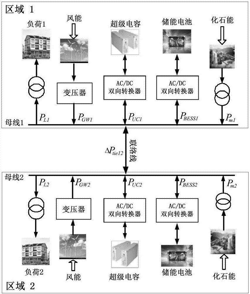
[0047] The multivariate complementary power system topology diagram of this embodiment is as follows figure 1 shown. The active power balance equation in the frequency domain is

[0048] P mi +P GWi +P BESSi +P UCi -P tie-ij =P Li (1)

[0049] Among them, i=1,2, j=1,2(i≠j),P mi is the traditional generator output power; P GWi is the fan output power, P BESSi is the output power of the battery energy storage system; P UCi is the output power of the supercapacitor; P tie-ij is the transmission power of the tie line; P Li is the area active load.

[0050] Although the power system is a nonlinear dynamic system, the power system model can be linearized when studying the problem of load frequency control because the load range is very small near the stable operating point.

[0051] 1) Traditional generator model

[0052] Most of the traditional generating sets are thermal generating sets, which are the main means of system frequency regulation and can provide stable...

) example 2

[0150] In this case, when t=5s Figure 10 The random load disturbances shown are added to both regions of the interconnected system. The value of ACE is in the auxiliary adjustment area, and the simulation results are shown in Figure 11.

[0151] In Fig. 11, the maximum frequency deviations of the proposed method, SM LFC and PI LFC with hybrid energy storage are 0.188 Hz, 0.28 Hz and 0.34 Hz, respectively. Obviously, the proposed method is more responsive and has less overshoot than the other two control methods. In SM LFC, the maximum frequency deviation of the system is greater than ±0.2Hz. Therefore, it is necessary for the supercapacitor to act immediately and absorb power. After that, the traditional generator adjusts its output power under the action of the sliding mode load frequency controller. The combination of supercapacitors and conventional generators can effectively improve the power quality of the system. In addition, compared with the PI LFC with hybrid en...


PUM


Abstract

The invention relates to a multi-area power system load frequency control method. A power system comprises a plurality of areas interconnected by connecting lines; and each area comprises a conventional generator, a super capacitor, a battery energy storage system and a wind generator. The multi-area power system load frequency control method is characterized by comprising the step of: according to a control interval in which a value of an ACE (Area Control Error) is positioned, enabling output power of a frequency regulating device to be correspondingly regulated, and enabling a system frequency error to be kept in a normal range. Compared with the prior art, according to the multi-area power system load frequency control method disclosed by the invention, different control strategies are adopted according to the control interval of the ACE. The control strategies effectively reduce a system frequency error, improve stability of the power system and reduce cost of power grid construction.

Description

technical field [0001] The invention relates to a load frequency control method of a power system, in particular to a load frequency control method of a multi-domain power system. Background technique [0002] Frequency is one of the important indicators to measure the safe and stable operation of power system. In order to ensure the quality of electric energy in the power system, it is very necessary to maintain the active power balance of the system. The depletion of fossil energy and the rapid deterioration of the global environment have led to the vigorous development of renewable energy, such as wind energy, solar energy, and tidal energy. As a clean and renewable energy source, wind energy occupies an important position in the energy structure. In recent years, wind energy penetration has grown rapidly around the world. However, the fluctuation and uncertainty of wind energy make the system frequency fluctuate greatly. Therefore, system frequency instability is an ...

Claims


Application Information

Patent Timeline
Patent Type & Authority Applications(China)
IPC IPC(8): H02J3/24
CPCH02J3/24H02J2203/20
Inventor 米阳郝学智马超何星瑭韩云昊苏向敬李振坤
Owner SHANGHAI UNIVERSITY OF ELECTRIC POWER
Learn More