Photovoltaic system and tracking mechanism thereof

A tracking mechanism and photovoltaic technology, which is applied to the support structure of photovoltaic modules, photovoltaic power generation, photovoltaic modules, etc., can solve the problems of easy aging and wear of plastic bearings, misalignment of rotation centers, and unfavorable force on the tracking mechanism, so as to avoid longevity. shorter effect

Pending Publication Date: 2017-10-24
ARCTECH SOLAR HLDG CO LTD
View PDF5 Cites 7 Cited by
  • Summary
  • Abstract
  • Description
  • Claims
  • Application Information

AI Technical Summary

Problems solved by technology

[0003] The existing tracking support for photovoltaic power generation usually installs the main beam on the column, and the main beam and the column support are provided with plastic bearings, so that the main beam can rotate on the column, and the photovoltaic system is generally used outdoors. The main beam and its plastic bearings Bearings need to bear a certain load, and under the harsh working environment in the field, the plastic bearings on the main beam are prone to aging and wear
Moreover, in the existing photovoltaic power generation system, the center of gravity of the main girder and the photovoltaic module does not coincide with the rotation center of the main girder, which will cause the gravity of the main girder and photovoltaic Beams generate additional torque, which is detrimental to the force of the tracking mechanism

Method used


Image

  • Photovoltaic system and tracking mechanism thereof
  • Photovoltaic system and tracking mechanism thereof
  • Photovoltaic system and tracking mechanism thereof

Examples


Embodiment 1

[0037] This specific embodiment discloses a photovoltaic tracking mechanism, which includes a column, a transmission mechanism and a driver. The driver is fixed on the column, the driver is connected with the transmission mechanism, and the driver drives the transmission mechanism. The transmission mechanism includes a main girder connecting rod, a first strut, a driving connecting rod and a second strut, and the main girder connecting rod, the first strut, the driving connecting rod and the second strut are sequentially hinged to form a four-bar linkage mechanism, The connecting rod of the main beam is provided with a mounting part for fixing and installing the main beam. The hinge points of the connecting rod of the main beam and the first strut and the hinge points of the connecting rod of the main beam and the second strut are respectively located on both sides of the mounting part. The connecting rod is connected with the output end of the driver.

[0038] When the photo...

Embodiment 2

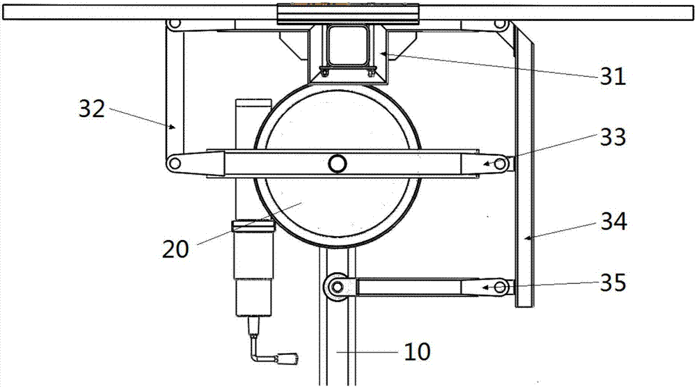
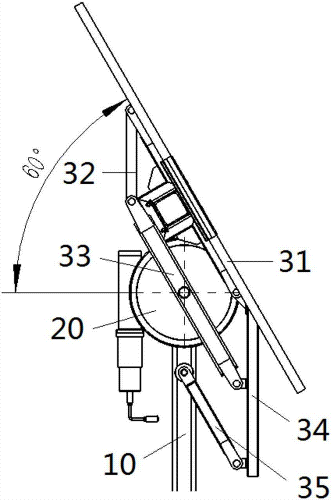
[0041] Such as Figures 1 to 5 As shown, this specific embodiment discloses a photovoltaic tracking mechanism. Same as the first embodiment, in this specific embodiment, the photovoltaic tracking mechanism also includes a column 10 , a transmission mechanism and a driver 20 . Such as Figures 1 to 4 As shown, the driver 20 is fixed on the column 10, the driver 20 is connected with the transmission mechanism, and the driver 20 drives the transmission mechanism. The transmission mechanism comprises a main beam connecting rod 31, a first strut 32, a driving connecting rod 33 and a second strut 34, and the main beam connecting rod 31, the first strut 32, the driving connecting rod 33 and the second strut 34 are sequentially hinged Form a four-bar linkage mechanism. The driving link 33 is connected with the output end of the driver 20 .

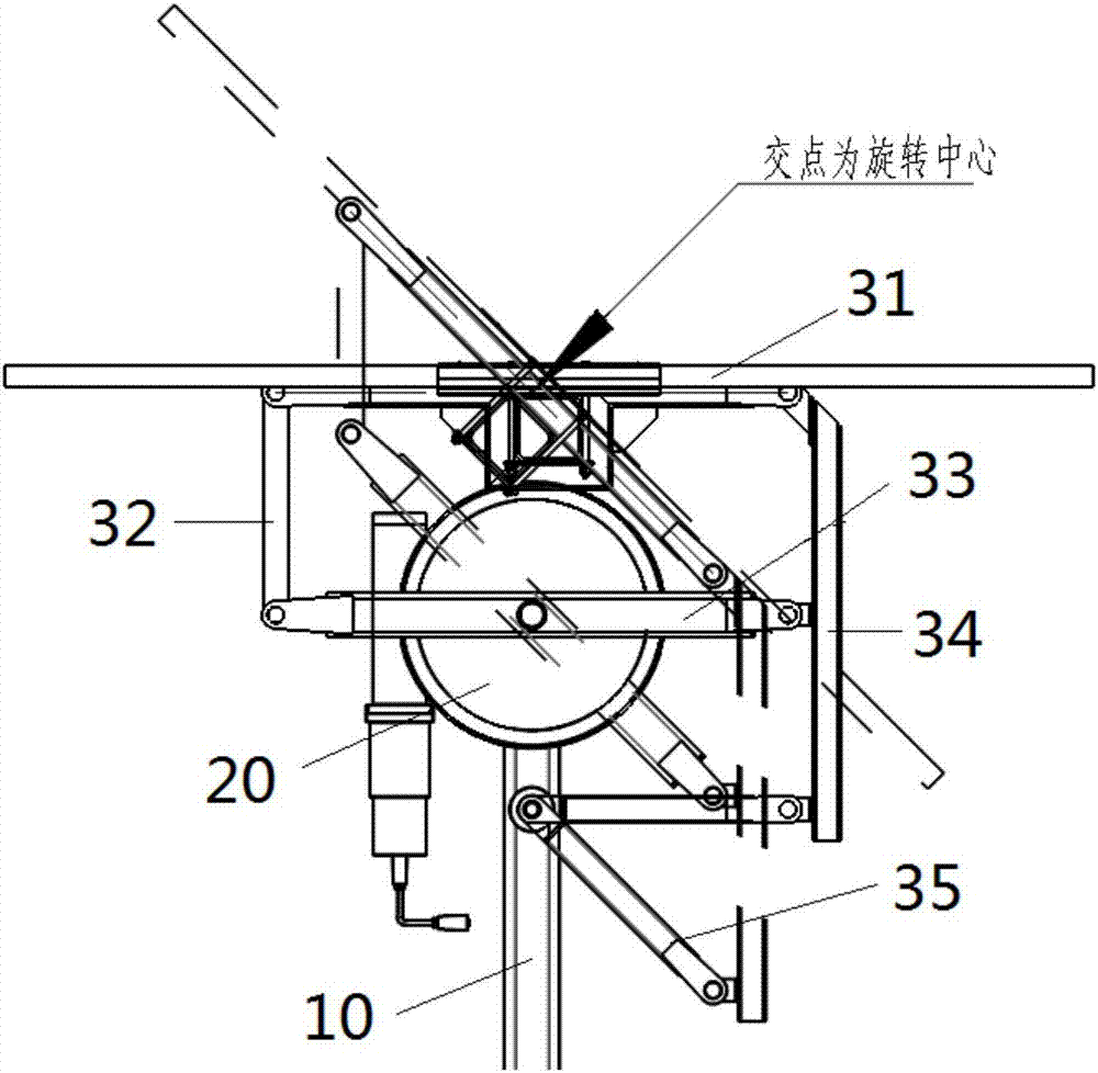
[0042] Such as figure 2 As shown, the schematic diagrams of the main girder connecting rod in the initial state and the rotating state, the i...

Embodiment 3

[0048] Embodiment 3 discloses another specific embodiment of the photovoltaic tracking mechanism of the present invention, its specific structure is basically the same as that of the photovoltaic tracking mechanism in Embodiment 2, the difference is that the structure of the main beam connecting rod 31 of the two is different .

[0049] Such as Figure 6 , 7 As shown, in this specific embodiment, the main beam connecting rod 31 is a rod-shaped structure, and the surface of the rod-shaped structure away from the column 10 is a plane. bolt assembly. That is to say, in this embodiment, the main beam connecting rod 31 is not provided with a groove for installing the main beam, but the main beam connecting rod 31 is directly connected to the main beam through a bolt assembly. Below the rod 31.


PUM


Abstract

The invention discloses a photovoltaic system and a tracking mechanism thereof. The tracking mechanism comprises a stand column, a transmission mechanism and a driver, wherein the driver is fixed on the stand column and is connected with the transmission mechanism; the transmission mechanism comprises a main beam connecting rod, a first supporting rod, a drive connecting rod and a second supporting rod which are sequentially hinged to form a four-rod linkage mechanism; a mounting part used for fixedly mounting a main beam is arranged on the main beam connecting rod; hinge points of the main beam connecting rod and the first and second supporting rods are positioned on both sides of the mounting part separately; and the drive connecting rod is connected with an output end of the driver. The photovoltaic system and the tracking mechanism thereof omit a plastic bearing between the main beam and the stand column, thereby avoiding the influence of short service life and unstable structure of the plastic bearing on the whole set of tracking mechanism; and the photovoltaic system and the tracking mechanism thereof enable a rotating center of the four-rod linkage mechanism to coincide with gravity centers of the main beam and a photovoltaic assembly, thereby avoiding extra torque generated to the main beam by gravity of the main beam and the photovoltaic assembly when the main beam and the photovoltaic assembly rotate.

Description

technical field [0001] The invention relates to system structure design in the field of photovoltaics, in particular to a photovoltaic system and a tracking mechanism thereof. Background technique [0002] Photovoltaic tracking mechanisms are photovoltaic systems that automatically track the sun and improve overall power generation. The automatic tracking mechanism of the solar photovoltaic array tracks the movement of the sun in real time, so that the sunlight directly shines on the photovoltaic array, thereby increasing the amount of solar radiation received by the photovoltaic array and improving the overall power generation of the solar photovoltaic power generation system. There are four solar photovoltaic automatic tracking mechanisms that are widely used, including horizontal single-axis tracking, double-column oblique single-axis tracking, vertical single-axis tracking and dual-axis tracking, of which horizontal single-axis tracking and inclined single-axis tracking,...

Claims


Application Information

Patent Timeline
IPC IPC(8): H02S20/32H02S40/10
CPCH02S20/32H02S40/10Y02E10/50
Inventor 蔡浩姚全忠
Owner ARCTECH SOLAR HLDG CO LTD
Why Eureka
Try Eureka