Multi-beam satellite array antenna pattern integrated method based on particle swarm optimization method

A technology of pattern synthesis and particle swarm optimization, applied in diversity/multi-antenna systems, genetic models, genetic laws, etc., can solve problems such as slow convergence speed and local optimal solutions, and achieve improved convergence speed and improved beamforming. Effects, Effects of Precise Beam Design

Active Publication Date: 2017-10-24
HARBIN INST OF TECH
View PDF6 Cites 27 Cited by
  • Summary
  • Abstract
  • Description
  • Claims
  • Application Information

AI Technical Summary

Problems solved by technology

[0011] The purpose of the present invention is to solve the problem of slow convergence speed and easy to fall into local optimal solution when using traditional particle swarm optimization algorithm for satellite carrier beamforming, and propose a multi-beam satellite array antenna pattern synthesis based on particle swarm optimization algorithm method

Method used


Image

  • Multi-beam satellite array antenna pattern integrated method based on particle swarm optimization method
  • Multi-beam satellite array antenna pattern integrated method based on particle swarm optimization method
  • Multi-beam satellite array antenna pattern integrated method based on particle swarm optimization method

Examples


specific Embodiment approach 1

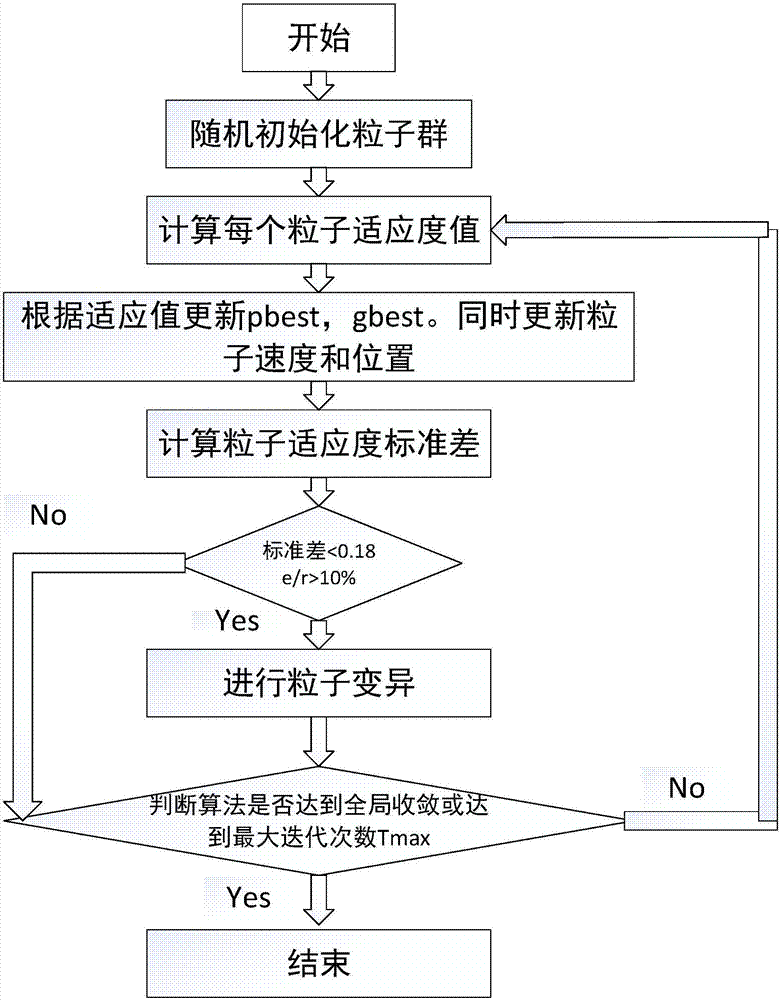
[0043] Specific implementation mode one: as figure 1 and figure 2 As shown, the multi-beam satellite array antenna pattern synthesis (Antenna pattern synthesis) method based on the particle swarm optimization algorithm includes the following steps:

[0044] Step 1. For the phased array antenna arranged in a straight line with N array elements, initialize the array element amplitude vector w and phase value vector p;

[0045] Step 2. Calculate the position and velocity of the amplitude and phase of each particle in the population; the particle represents the amplitude and phase value of the antenna element;

[0046]Step 3. Calculate the fitness value s and iterative error e of each particle in the population; compare the iterative error e obtained by the ith calculation with the iterative error e obtained by the i-1th calculation, and select the particle with the smaller iterative error e The corresponding array element amplitude vector w and phase value vector p are used a...

specific Embodiment approach 2

[0069] Specific embodiment 2: The difference between this embodiment and specific embodiment 1 is that in the first step, the value of the array element amplitude vector w is initialized to any value in [0,1], and the value of the phase value vector p is It is any value in [0,360].

[0070] Other steps and parameters are the same as those in Embodiment 1.

specific Embodiment approach 3

[0071] Specific embodiment three: the difference between this embodiment and specific embodiment one or two is: the specific process of calculating the position and velocity of each particle amplitude and phase in the population in the second step is:

[0072]

[0073] V 0 a =rand(y,T)-0.5*ones(y,T)

[0074]

[0075] V 0 p =360*(rand(y,T)-0.5*ones(y,T))

[0076] Where y is the number of particle swarms, T is the number of iterations, and N is the number of antenna elements; where represents the initial value of the position of the particle amplitude, V 0 a Represents the initial value of the velocity of the particle amplitude; represents the initial value of the position of the particle phase, V 0 p Represents the initial value of the velocity of the particle phase. The rand function in the formula can randomly generate a random number between [0,1], and the ones function generates a sequence of all 1 values.

[0077] Other steps and parameters are the same ...


PUM


Abstract

The invention provides a multi-beam satellite array antenna pattern integrated method based on a particle swarm optimization method, relates to the multi-beam satellite array antenna pattern integrated method, and aims at solving the problems that convergence speed is low and the process is liable to get into local optimum when spaceborne beam forming is performed by using the conventional particle swarm optimization method. The beams of special shape require to be designed for compensating the path loss caused by the low-orbit satellite near-far effect. The solution of the array element amplitude and phase is simulated as the search process of the bird flock for the food in the natural world by using the heuristic algorithm particle swarm optimization algorithm. The initial population number, the particle number and the iteration frequency are set and finally the excellent flat-topped beams and cosecant-squared beams can be obtained. The requirement of isoflux coverage can be met. The optimal solution can be obtained through convergence after 300 times of iteration, while convergence can be obtained after more than 500 times of iteration by the conventional algorithm. The multi-beam satellite array antenna pattern integrated method based on the particle swarm optimization method is used for the field of satellite communication.

Description

technical field [0001] The invention relates to a multi-beam satellite array antenna pattern synthesis method. Background technique [0002] In today's satellite communication system, low-orbit satellites have special advantages that other orbit satellites do not have, such as low path loss and small propagation delay. For GEO satellites and MEO satellites, the opening angle of the satellite beam coverage area is very small, and the difference in the free space path from the sub-satellite point to the edge of the beam coverage is negligible, but for low-orbit satellites, the difference in path loss cannot be ignored. In order to ensure that the end users in the satellite coverage area can enjoy the same quality of service no matter whether they are at the center of the beam or at the edge of the beam. It is necessary to use multi-beam satellites to provide different degrees of beam coverage to the coverage area, and to perform beamforming on the coverage beams, so that the ...

Claims


Application Information

Patent Timeline
Patent Type & Authority Applications(China)
IPC IPC(8): H04B7/06H04B7/08H04B7/185G06N3/12
CPCG06N3/126H04B7/0617H04B7/086H04B7/18519
Inventor 杨明川周赫张宇萌张淑静马晨邵欣业
Owner HARBIN INST OF TECH
Why Eureka
Try Eureka