Eureka AIR delivers breakthrough ideas for toughest innovation challenges, trusted by R&D personnel around the world.

Honeycomb image element array, image sensor and acquisition method based on dislocation image enhancement

An image sensor and pixel array technology, applied in the field of image sensors, can solve the problems of reduced signal-to-noise ratio, large pixel spacing, and increased volume, quality, and cost of the whole device, and achieves improved signal-to-noise ratio and resolution. Effect

Inactive Publication Date: 2017-10-24
XINFOO SENSOR TECH CO LTD
View PDF15 Cites 0 Cited by
  • Summary
  • Abstract
  • Description
  • Claims
  • Application Information

AI Technical Summary

Problems solved by technology

There are generally two ways to improve the resolution and image quality of the image sensor. The first is to increase the focal length of the optical system, but this will greatly increase the volume, quality and cost of the whole device, and the optical system must be redesigned. The second is to reduce the pixel size of the image sensor. In general, if the optical-mechanical system remains unchanged, if the pixel size is reduced, the MTF of the imaging system will decrease and the signal-to-noise ratio will decrease. image quality
[0003] In terms of microwave, THz, and far-infrared detection, due to the special properties of these spectral bands and the limitations of related spectral band photosensitive materials, compared with near-infrared, visible light, ultraviolet, X-ray and other spectral band detectors, microwave, THz, far-infrared The pixel size of the detector is generally large, and the pixel spacing is also large. Under the same optical system, the resolution of images in the microwave, THz, and far-infrared bands is low. Using traditional methods to improve the spatial resolution will cause the overall The volume and weight of the machine are doubled, the optical-mechanical structure is difficult to realize, and the requirements for the user's application are more stringent

Method used


Image

  • Honeycomb image element array, image sensor and acquisition method based on dislocation image enhancement
  • Honeycomb image element array, image sensor and acquisition method based on dislocation image enhancement
  • Honeycomb image element array, image sensor and acquisition method based on dislocation image enhancement

Examples


Embodiment Construction

[0030] In order to make the purpose, technical solutions and advantages of the embodiments of the present invention more clear, the technical solutions in the embodiments of the present invention will be clearly and completely described below in conjunction with the drawings in the embodiments of the present invention. Based on the embodiments of the present invention, all other embodiments obtained by persons of ordinary skill in the art without creative efforts fall within the protection scope of the present invention.

[0031] The development of image sensors has become very popular today. The image acquisition range spans multiple frequency bands. The common frequency spectrum areas include microwave, THz, infrared, visible light, ultraviolet, X-ray, etc. The traditional pixel structure adopts horizontal row-by-row arrangement. Currently, Already very mature. There are generally two ways to improve the resolution and image quality of the image sensor. The first is to chang...


PUM


Abstract

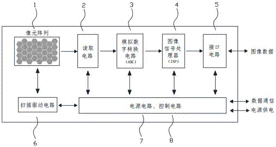
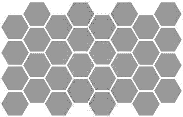
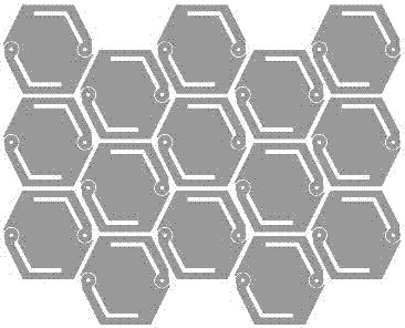
The invention relates to the technical field of image sensors, and particularly relates to a honeycomb image element array, an image sensor and an acquisition method based on dislocation image enhancement. Multiple honeycomb image elements are arranged on a two-dimensional plane in a repeated and dislocation mode to form the image element array. The image sensor comprises the honeycomb image element array, a scanning drive circuit, a reading circuit, an analog-to-digital conversion (ADC) circuit, an image signal processor (ISP), a power supply circuit for power supply of the whole chip and a control circuit for intelligent control of the whole chip. Through the unique dislocation honeycomb image element array, in a condition of the same image element number or nearly the same image element number, the image resolution can be greatly improved, the focus of the optical system of the whole machine device is reduced, the size, the weight and the cost of the whole machine device are reduced, and functions of improving the resolution, the signal-to-noise ratio (S / N) and the isolation degree and reducing the cost, the size and the weight are realized.

Description

technical field [0001] The invention relates to the technical field of image sensors, in particular to a honeycomb pixel array, an image sensor and an acquisition method based on dislocation and image enhancement. Background technique [0002] The development of image sensors has become very popular today. The image acquisition range spans multiple frequency bands. The common frequency spectrum areas include microwave, THz, infrared, visible light, ultraviolet, X-ray, etc. The traditional pixel structure adopts horizontal row-by-row arrangement. Currently, Already very mature. There are generally two ways to improve the resolution and image quality of the image sensor. The first is to increase the focal length of the optical system, but this will greatly increase the volume, quality and cost of the whole device, and the optical system must be redesigned. The second is to reduce the pixel size of the image sensor. In general, if the optical-mechanical system remains unchange...

Claims


Application Information

Patent Timeline
IPC IPC(8): H04N5/378H04N5/369H01L27/146
CPCH01L27/14605H01L27/14607H01L27/14636H04N25/70H04N25/75
Inventor 赵照
Owner XINFOO SENSOR TECH CO LTD
Why Eureka
Eureka Blog
Learn More