Vaneless blood pump

A technology of blood pumps and blades, applied in the field of bladeless blood pumps, can solve the problems of being unable to supply for a long time, prone to hemolysis, etc., and achieve the effects of not being prone to hemolysis and thrombosis, less blood damage, and ensuring quality

Inactive Publication Date: 2017-10-27
GUANGDONG SHUNDE IND DESIGN INST GUANGDONG SHUNDE INNOVATIVE DESIGN INST +1
View PDF9 Cites 1 Cited by
  • Summary
  • Abstract
  • Description
  • Claims
  • Application Information

AI Technical Summary

Problems solved by technology

[0003] Based on this, it is necessary to provide a bladeless blood pump that is not prone to hemolysis and can be supplied for a long time in view of the problems that blood is prone to hemolysis and cannot be supplied for a long time

Method used


Image

  • Vaneless blood pump
  • Vaneless blood pump
  • Vaneless blood pump

Examples


Embodiment 1

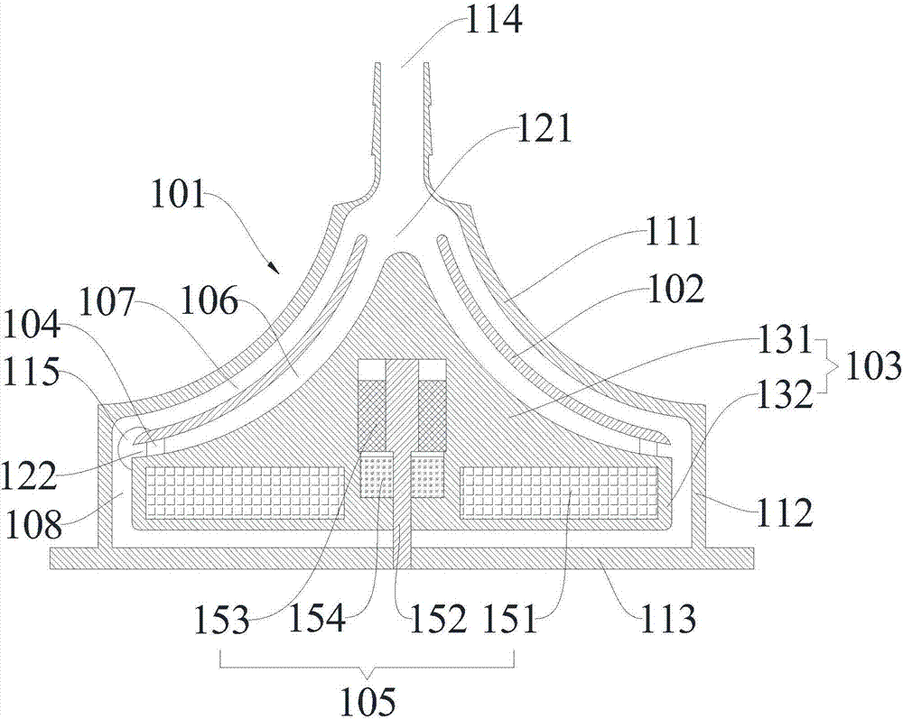
[0023] Please refer to figure 1 , the embodiment of the present invention discloses a bladeless blood pump, including a volute 101, a rotor 103, a flow guide assembly 104, a power device 105 and at least one partition 102, the volute 101 is provided with a first cavity and the first liquid inlet 114 and the first liquid outlet 115 communicating with the first cavity, the partition 102 and the rotor 103 are all arranged in the first cavity, and the partition 102 is set There is a second cavity and a second liquid inlet 121 and a second liquid outlet 122 communicating with the second cavity, the partition 102 is sleeved on the rotor 103, the partition 102 is connected with the The rotors 103 are fixedly connected by the guide assembly 104, the first laminar flow channel 106 is formed between the inner wall of the partition 102 and the outer wall of the rotor 103, and the outer wall of the partition 102 and the scroll A conveying channel 107 is formed between the inner walls of ...

Embodiment 2

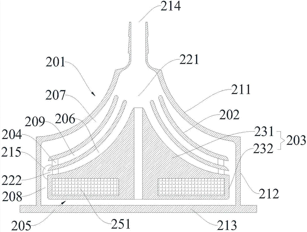
[0032] Please refer to figure 2 , the embodiment of the present invention discloses a bladeless blood pump, including a volute 201, a rotor 203, a flow guide assembly 204, a power device 205 and at least one partition 202, the volute 201 is provided with a first cavity and the first liquid inlet 214 and the first liquid outlet 215 communicating with the first cavity, the partition 202 and the rotor 203 are all arranged in the first cavity, and the partition 202 is set There is a second cavity and a second liquid inlet 221 and a second liquid outlet 222 communicating with the second cavity, the partition 202 is sleeved on the rotor 203, the partition 202 is connected with the The rotors 203 are fixedly connected through the guide assembly 204, the first laminar flow channel 206 is formed between the inner wall of the partition 202 and the outer wall of the rotor 203, and the outer wall of the partition 202 and the scroll A delivery channel 207 is formed between the inner wall...

Embodiment 3

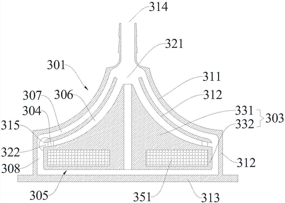
[0041] Please refer to image 3 , the embodiment of the present invention discloses a bladeless blood pump, including a volute 301, a rotor 303, a flow guide assembly 304, a power device 305 and at least one partition 302, the volute 301 is provided with a first cavity and the first liquid inlet 314 and the first liquid outlet 315 communicating with the first cavity, the partition 302 and the rotor 303 are all arranged in the first cavity, and the partition 302 is set There is a second cavity and a second liquid inlet 321 and a second liquid outlet 322 communicating with the second cavity, the partition 302 is sleeved on the rotor 303, the partition 302 is connected with the The rotors 303 are fixedly connected by the guide assembly 304, the first laminar flow channel 306 is formed between the inner wall of the partition 302 and the outer wall of the rotor 303, and the outer wall of the partition 302 and the scroll A delivery channel 307 is formed between the inner walls of t...


PUM


Abstract

The invention relates to a vaneless blood pump. The vaneless blood pump comprises a volute, at least one separating piece, a rotor, a diversion piece and a power device; the volute is provided with a first cavity, a first liquid inlet and a first liquid outlet, wherein the first liquid inlet and the first liquid outlet are communicated with the first cavity; the separating piece and the rotor are arranged in the first cavity; the separating piece is provided with a second cavity, a second liquid inlet and a second liquid outlet, wherein the second liquid inlet and the second liquid outlet are communicated with the second cavity; the rotor is sleeved with the separating piece and fixedly connected with the separating piece through the diversion piece; a laminar flow channel is formed between the inner wall of the separating piece and the outer wall of the rotor. By supplying blood in this mode, the blood which needs to be supplied can flow in a laminar flow state, so that phenomena of hemolysis and thrombosis do not occur to the blood easily; meanwhile, the blood is not squeezed in the laminar flow mode, the damage to the blood is relatively small, long-term blood supplying can be conducted, the requirements of long-term blood supplying can be met, and the quality of the blood is ensured.

Description

technical field [0001] The invention relates to a blood delivery device, in particular to a bladeless blood pump. Background technique [0002] In a conventional blood pump, the blood is pushed by the blades, and the blades will give the blood a relatively large driving force, but it will also bring relatively large disturbances, and the blood generally remains in a turbulent flow state. Due to the high speed of the impeller, the red blood cells in the blood, the blades and the pump wall will be damaged by impact, which will easily lead to damage to the red blood cells, and the hemolysis caused by the damage to the red blood cells is still very serious. This pump can only be used for a short period of time. It is not conducive to use in occasions that require a long-term stable blood supply (for example, in the case of liver perfusion and other situations that require blood supply for more than 24 hours, it is difficult to meet the requirements of the blade-propelled blood ...

Claims


Application Information

Patent Timeline
Patent Type & Authority Applications(China)
IPC IPC(8): A61M1/10
CPCA61M2206/11A61M60/205A61M60/419
Inventor 林超任晓龙
Owner GUANGDONG SHUNDE IND DESIGN INST GUANGDONG SHUNDE INNOVATIVE DESIGN INST
Why Eureka
Try Eureka