Curvature-adaptive pulley block

A self-adaptive, pulley block technology, applied in hoisting devices, portable hoisting devices, etc., can solve the problems of damage to the internal structure of the rope, excessive bending of the rope, and high production costs, reducing bending, improving bending, and low cost. Effect

Active Publication Date: 2017-10-27
THE FIRST INST OF OCEANOGRAPHY SOA
View PDF6 Cites 2 Cited by
  • Summary
  • Abstract
  • Description
  • Claims
  • Application Information

AI Technical Summary

Problems solved by technology

This type of cable is expensive to produce, and if the diameter of the pulley block is too small, the cable will bend excessively
Will destroy the internal structure of the rope and cause heavy losses

Method used


Image

  • Curvature-adaptive pulley block
  • Curvature-adaptive pulley block
  • Curvature-adaptive pulley block

Examples


Embodiment 1

[0029] The following is a description of Embodiment 1.

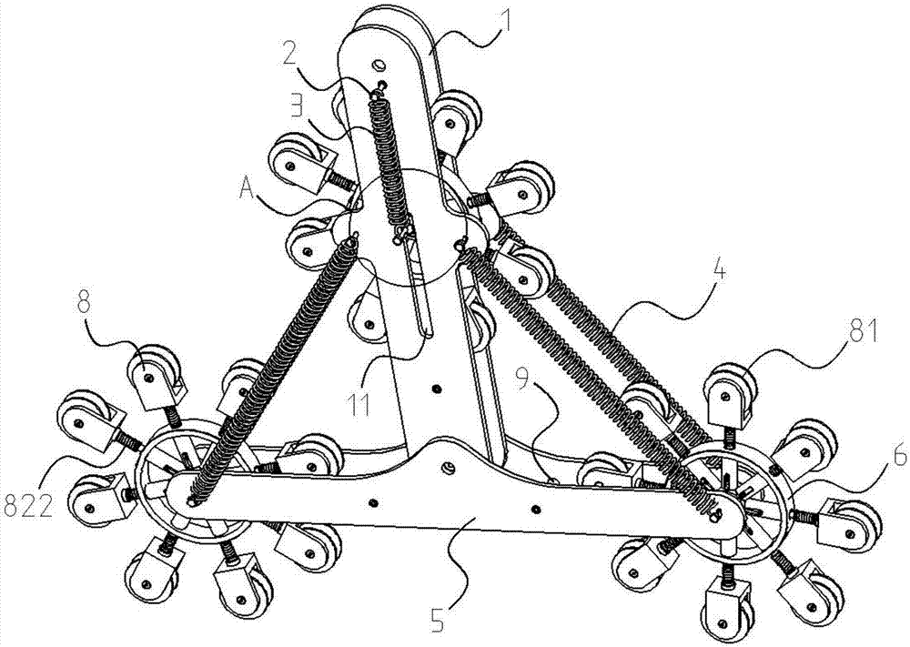
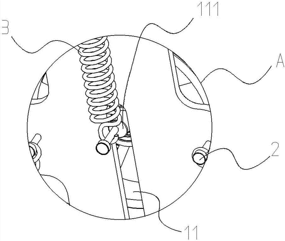
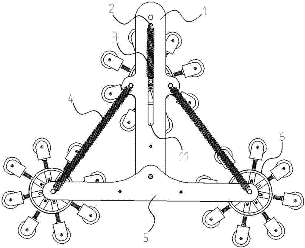
[0030] Such as Figure 1 to Figure 7 As shown, a curvature adaptive pulley block includes a vertical main suspension plate 1, a positioning track groove 11, a positioning sliding column 111, a tension spring fixing column 2, an upper tension spring 3, a return tension spring 4, and a lateral support end plate 5. Wheel-shaped installation body 6, bearing 7, pulley mounting seat 8, pulley 81, support rod 82, support sliding column 821, spring 822, reinforcement fixing rod 9, the vertical main suspension plate 1 and the lateral support end plate 5 are respectively provided with two pieces, two vertical main suspension plates 1 are opposite to two horizontal support end plates 5 and are connected and fixed through the reinforcing fixing rod 9 arranged in the middle, the bottom of the vertical main suspension plate 1 is connected with the horizontal support end plate 5 The middle positions of the support end plates 5 are axi...

Embodiment 2

[0035] The following is the description of the second embodiment.

[0036] In embodiment 2, for the same structure as in embodiment 1, the same labels are given, and the same description is omitted. The middle position of the vertical main suspension plate 1 and the lateral support end plate 5 is fixedly connected by a shaft connection, Omitting the two return springs 4 installed between the vertical main suspension plate 1 and the lateral support end plate 5 through the tension spring fixing column 2 reduces the production cost and at the same time achieves the effect of reducing the bending fatigue damage of the rope.

[0037] When this device is installed, after fixing the top of the vertical main suspension plate 1, the ropes are installed on the pulleys 81 provided outside the three wheel-shaped installation bodies 6, and the strengthening fixing rod 9 can be used for the vertical main suspension plate 1 and the horizontal direction. The support end plate 5 is effectively...


PUM


Abstract

The invention discloses a curvature-adaptive pulley block and belongs to the technical field of mechanical equipment. The curvature-adaptive pulley block comprises two vertical main suspension plates, two transverse support end plates, pulley mounting seats and reinforcing and fixing rods; the vertical main suspension plates are respectively connected with the transverse support end plates through the reinforcing and fixing rods, the vertical main suspension plates are connected with the transverse support end plates, wheel-shape mounting bodies are respectively mounted to two ends of the transverse support end plates and interval insides of the vertical main suspension plates, a pulley is coupled in one end of each pulley mounting seat while a support bar is arranged at the other end of the pulley mounting seat, the support bar is arranged in a hollow connecting rod in each wheel-shape mounting body, a bearing slide column arranged on the support bar is mounted in a sliding rail slot in the hollow connecting rod, and the support bar is further sleeved with a spring. By the arrangement, the problem about curvature fracture of a pulley rope resulting in large damage is solved; the curvature-adaptive pulley block is simple in structure and capable of effectively reducing the curvature of the working rope, and damage due to curvature fatigue is reduced.

Description

technical field [0001] The invention relates to a curvature adaptive pulley block, which belongs to the technical field of mechanical equipment. Background technique [0002] At present, the pulley block has been widely used in the field of mechanical equipment. It is one of the very common mechanisms in hoisting, transmission, and towing. It can not only save the traction force applied by extracting heavy objects, but also change the direction of the force. In the assembly of large machinery And plays an important role in the process of parts deployment. For example, ships, aerospace, large generator sets, etc. [0003] In the prior art, the pulleys generally work together with the cables. Since the cables are wound on the pulleys, if the diameter of the pulleys is too small, it will cause bending fatigue damage to the cables and greatly affect the service life of the cables. Especially in the field of ships, composite cables with functions such as load bearing, power tra...

Claims


Application Information

Patent Timeline
Patent Type & Authority Applications(China)
IPC IPC(8): B66D3/06
CPCB66D3/06
Inventor 官晟王岩峰王冠琳范斌王新怡
Owner THE FIRST INST OF OCEANOGRAPHY SOA
Why Eureka
Try Eureka