Engine cylinder block water jacket

A technology for engine cylinders and cylinder blocks, applied in engine components, machines/engines, cylinders, etc., can solve problems such as weakened stiffness, low coolant flow rate, permanent deformation of the top of the cylinder block, etc., to improve heat exchange efficiency and meet cooling needs. , The effect of reducing the risk of pulling the cylinder

Inactive Publication Date: 2017-11-03
CHERY AUTOMOBILE CO LTD
View PDF8 Cites 4 Cited by
  • Summary
  • Abstract
  • Description
  • Claims
  • Application Information

AI Technical Summary

Problems solved by technology

When the engine performance improves, the explosion pressure and thermal load continue to increase, which will lead to a local overheating area in the cylinder, the highest temperature of the cylinder wall exceeds the coking temperature of the engine oil, the oil film is destroyed, the piston ring cannot be well lubricated, and the carbon deposit in the piston ring groove is serious , resulting in cylinder strain
At the same time, the high-temperature area between the cylinders is too large, and the cylinder barrel is severely deformed, which may cause high-temperature sticking between the piston, piston skirt and the cylinder wall, and cylinder scuffing; it may also cause the piston ring to be poorly sealed, resulting in large piston air leakage. Engine failure such as burning oil
When the cooling of the engine is poor and the temperature of the cylinder wall is high enough, a large amount of thermal expansion will be caused between the cylinders. The cylinder block and cylinder head in contact with the cylinder gasket at the position between the cylinders will be greatly deformed, or even fail; the cylinder wall is high temperature, and the engine is prone to detonation, or even super detonation, which will affect the piston, connecting rod, crankshaft, cylinder block, cylinder head and other components reliability
[0003] In the prior art, there are three commonly used methods to strengthen the cooling between cylinders: 1. Directly cast through the cylinders by casting, and the coolant in the cooling water jacket can directly cool the cylinders; but casting requires a large distance between the cylinders. , the nose bridge area is wide, which is common in medium and large diesel engines; 2. The top of the cylinder is slotted, and the slot is suitable for aluminum cylinders with a small cylinder center distance, but because the top of the cylinder is machined, the slot width is limited , after processing, the groove bottom forms a sudden change in stiffness, which is easy to cause stress concentration, and the ignition usually occurs when the piston runs to the top dead center. As a result, the rigidity of the top of the cylinder is weakened. Under the repeated action of high explosion pressure, the top of the cylinder is prone to permanent deformation and there is a risk of failure; 3. Add V-shaped and Y-shaped inclined water holes between the two cylinders. Traditional inclined water holes The water inlet and outlet of the water inlet and outlet are arranged in the cylinder water jacket on the intake and exhaust sides. Since they are all inside the water jacket of the cylinder body, the pressure difference between the inlet and outlet is limited, resulting in a low flow rate of the coolant in the inclined water hole. Although this kind of inclined water hole can cool The local high temperature between the two cylinders, but the cooling capacity is limited, and the temperature between the cylinders will still maintain a high temperature, which cannot meet the cooling requirements

Method used


Image

  • Engine cylinder block water jacket
  • Engine cylinder block water jacket
  • Engine cylinder block water jacket

Examples


Embodiment Construction

[0011] Combine below Figure 1-Figure 4 The present invention is discussed in further detail.

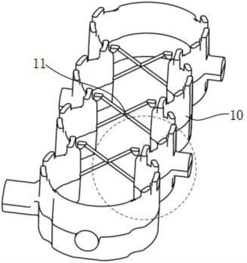
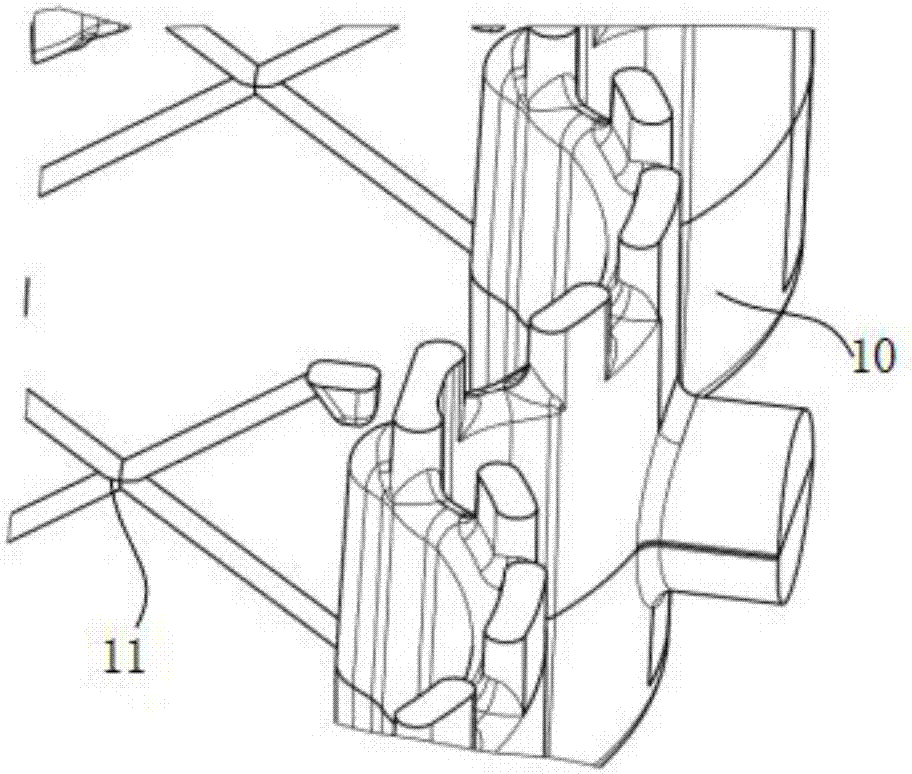
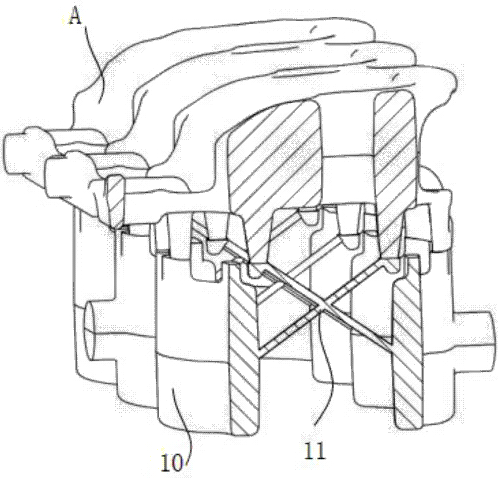
[0012] A water jacket for an engine cylinder block includes a water jacket body 10 surrounding the outer circumference of the cylinder bore of the cylinder block 20 to form a circulating cooling cavity. The nose area of ​​the water jacket body 10 is provided with X-shaped water passing through the inlet and exhaust sides. Hole 11, the lower end of the X-shaped water through hole 11 communicates with the water jacket body 10, and the upper end extends to the position of the cylinder head water jacket A and communicates with the cylinder head water jacket A. In the above solution, using the pressure difference of the coolant between the cylinder block 20 and the cylinder head, the minimum flow rate of the coolant in the X-shaped water hole 11 is greatly increased, and the heat exchange efficiency with the cylinder block 20 is improved. The ability of hole 11 to control the high temperat...


PUM


Abstract

The invention aims to provide an engine cylinder block water jacket capable of increasing flow rate of cylinder-to-cylinder cooling fluid and effectively lowering cylinder-to-cylinder temperature. The engine cylinder block water jacket comprises a water jacket body surrounding the peripheries of cylinder holes of cylinder blocks to form a circulating cooling cavity, X-shaped water through holes communicating the air intake side with the exhaust side are formed in the bridge zone of the water jacket body, and the lower end of each X-shaped water through hole is communicated with the water jacket body while the upper end extends to the position of a cylinder head water jacket and is communicated with the cylinder head water jacket. By the aid of pressure difference of cooling fluid between the cylinder blocks and cylinder heads, the lowest flow rate of cooling fluid in the X-shaped water through holes is increased greatly, heat exchange efficiency between the cylinder blocks is improved, the capacity of the X-shaped water through holes for controlling the high temperature area between two cylinders is enhanced, cylinder-to-cylinder temperature is maintained within an adequate range, and cooling requirements are met; the cylinder wall surfaces is prevented from being at high temperature exceeding the engine oil coking temperature to destroy lubricating oil film between cylinder barrels and pistons as well as cylinder barrels and piston rings, and risk of cylinder scoring is reduced.

Description

Technical field [0001] The invention relates to the technical field of automobile engines, in particular to an engine cylinder block water jacket. Background technique [0002] The water jacket of the engine cylinder block exists in the space area between the cylinder bore and the outer wall of the cylinder, and its main function is to cool the cylinder bore during engine operation. At present, the engine is designed to be small, compact, and lightweight. At the same time, the water jacket design is required to meet the characteristics of small water jacket volume, fast heat dissipation in key high-temperature areas, and small impact on structural strength. When the engine performance increases, the explosion pressure and thermal load continue to increase, which will cause local overheating areas in the cylinder, the maximum temperature of the cylinder wall exceeds the oil coking temperature, the oil film is destroyed, the piston ring cannot be well lubricated, and the piston rin...

Claims


Application Information

Patent Timeline
IPC IPC(8): F02F1/10
CPCF02F1/10
Inventor 齐少虎吕希祥桑毅昂亮周君
Owner CHERY AUTOMOBILE CO LTD
Why Eureka
Try Eureka