Carbon dioxide four-stage rotor type compression-expansion machine

A technology of compressing expander and carbon dioxide, applied in compressors, rotary piston machines, rotary piston engines, etc., can solve the problems of low cycle efficiency of energy loss, stagnation of working fluid flow, increase of complexity, etc. , the effect of reducing friction and reducing cooling loss

Inactive Publication Date: 2017-11-03
TIANJIN UNIV
View PDF6 Cites 0 Cited by
  • Summary
  • Abstract
  • Description
  • Claims
  • Application Information

AI Technical Summary

Problems solved by technology

[0004] However, there are several problems in the transcritical cycle of carbon dioxide: 1. The critical temperature of carbon dioxide is low, and there is a large energy loss in the throttling near the critical area. The cycle efficiency is low. In order to reduce the throttling loss caused by throttling, in the carbon dioxide system, The measure of replacing the throttle valve with an expander is often used, but how to actually use the recovered expansion work is a problem that needs to be solved; 2. At the inlet of the expander, the intake air volume needs to be controlled by a cam and a valve stem, and the system needs to be installed with a cam valve stem , the complexity is increased, and there is a certain void volume in the cam valve stem control structure, which may lose part of the expansion work and increase the loss; 3. The intake air volume is controlled by the cam and the valve stem, and the flow of the working medium is stopped, resulting in pressure pulsation

Method used


Image

  • Carbon dioxide four-stage rotor type compression-expansion machine
  • Carbon dioxide four-stage rotor type compression-expansion machine
  • Carbon dioxide four-stage rotor type compression-expansion machine

Examples


Embodiment Construction

[0029] In order to further understand the content, characteristics and effects of the present invention, the following examples are given, and detailed descriptions are as follows in conjunction with the accompanying drawings:

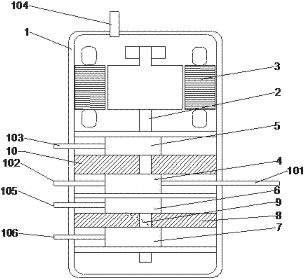
[0030] Such as figure 1 As shown, this embodiment discloses a carbon dioxide four-stage rotor type compression expander, which includes a housing 1, a motor part, a compression part, and an expansion part are arranged inside the housing 1, and the motor part, the compression part, and the expansion part are installed in the housing. 1 The interior is arranged from top to bottom, and separated from each other by baffles.

[0031]The motor part is set on the top of the housing 1, including the main shaft 2 and the coil 3, the coil 3 is wound on the main shaft 2, and the second compression cylinder 5 of the compression part, the first compression cylinder 4 and the expansion part are installed in sequence on the main shaft 2 The first expansion cylinder ...


PUM


Abstract

The invention belongs to the technical field of air conditioner refrigeration and discloses a carbon dioxide four-stage rotor type compression-expansion machine. A motor part, a compression part and an expansion part are arranged in a shell; the motor part comprises a main shaft and a coil wound on the main shaft; the compression part comprises a rotor type first compression cylinder and a rotor type second compression cylinder, and the first compression cylinder and the second compression cylinder are both installed on the main shaft and are each provided with an eccentric wheel, a sliding piece, a rolling ring and a rolling ball; the expansion part comprises a rotor type first expansion cylinder and a rotor type second expansion cylinder, and the first expansion cylinder and the second expansion cylinder are both installed on the main shaft and are each provided with an eccentric wheel, a sliding piece, a rolling ring and a rolling ball; and a partition plate with a middle channel is arranged between the first expansion cylinder and the second expansion cylinder. The carbon dioxide four-stage rotor type compression-expansion machine can fully recycle and utilize the expansion work, and reduce the loss of the cold energy; and the gap volume is reduced, and the loss of the expansion work is reduced; and meanwhile, the gas sucking amount of the expansion machine is controlled, and the loss of the cold energy is reduced.

Description

technical field [0001] The invention belongs to the technical field of air-conditioning and refrigeration, and more specifically relates to a carbon dioxide four-stage rotor-type compressor-expander, which is used for recovering expansion work, reducing cooling loss, and improving work efficiency. Background technique [0002] As global warming and ozone depletion have attracted great attention, CFCs and HCFCs refrigerants are being phased out. The Kigali Amendment to the Montreal Protocol on Substances that Deplete the Ozone Layer states that reducing emissions of potent greenhouse gases, hydrofluorocarbons (HFCs), will prevent global warming by 0.5°C by the end of the century. The core content is: developed countries will begin to gradually reduce HFCs before 2019; developing countries will freeze the consumption of HFCs from 2024, and some developing countries need to freeze consumption in 2028. By the late 2040s, all Party countries are expected to consume no more than ...

Claims


Application Information

Patent Timeline
IPC IPC(8): F04C18/344F04C23/02F01C1/344F01C13/04F25B31/00
Inventor 马一太李敏霞王派詹浩淼陈齐飞李双俊邵亚伟张正韬李昱翰
Owner TIANJIN UNIV
Why Eureka
Try Eureka