A method for locating leakage of gas pipeline based on vibration wave

A gas pipeline and positioning method technology, which is applied in the pipeline system, gas/liquid distribution and storage, mechanical equipment, etc., can solve the problems of pipeline leakage and positioning, the difficulty of long-term detection, and the consumption of manual labor, etc., to achieve The effect of reducing work input, reducing impact, and reducing the demand for manpower and material resources

Active Publication Date: 2022-07-19
ANHUI UNIV OF SCI & TECH
View PDF10 Cites 0 Cited by
  • Summary
  • Abstract
  • Description
  • Claims
  • Application Information

AI Technical Summary

Problems solved by technology

Ground surface detection is to detect the possible leakage sites manually on the ground through direct observation, using instruments or building pipeline models, mainly including manual inspection method, pipeline transient model method and gas imaging method, etc. Among them, manual inspection method consumes manual labor The cost and capital are large, and long-term detection cannot be carried out, and the work efficiency is low; the pipeline transient change model method has many factors that affect the dynamic detection of pipelines, and it is difficult to detect and locate pipeline leakage with this method, and the error is also high; gas imaging The method can only initially locate the leakage area, and more accurate positioning needs to be processed and verified in combination with other methods in the later stage.
In addition, the detection method of the outer wall of the pipeline and the detection method of the inner wall of the pipeline also have defects that cannot be ignored in terms of positioning accuracy, adaptability, cost, etc.
[0004] The invention patent application with the publication number CN104654024A discloses a generalized regression neural network leak location analysis method for urban gas pipelines. By arranging pressure sensors upstream and downstream of the pipeline, the leakage point can be located by the time difference of the leakage vibration signals received by the two pressure sensors. , but this method is only suitable for straight pipelines, and sensors need to be deployed in the early stage of construction, otherwise a large number of sensors will be required in the later stage of construction, and the applicability is poor

Method used


Image

  • A method for locating leakage of gas pipeline based on vibration wave
  • A method for locating leakage of gas pipeline based on vibration wave
  • A method for locating leakage of gas pipeline based on vibration wave

Examples


Embodiment Construction

[0031] In order to make the objectives, technical solutions and advantages of the present invention more clearly understood, the present invention will be further described in detail below in conjunction with specific embodiments and with reference to the accompanying drawings.

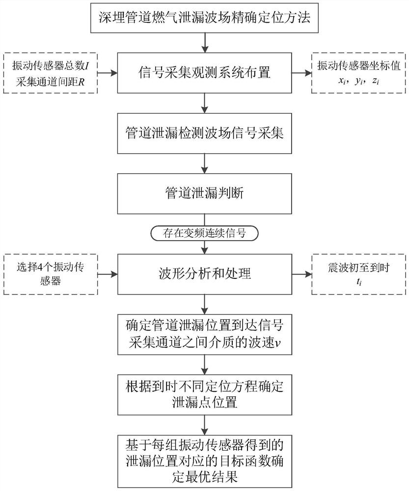
[0032] like figure 1 As shown, this embodiment provides a method for locating gas pipeline leakage based on vibration waves, including the following steps:

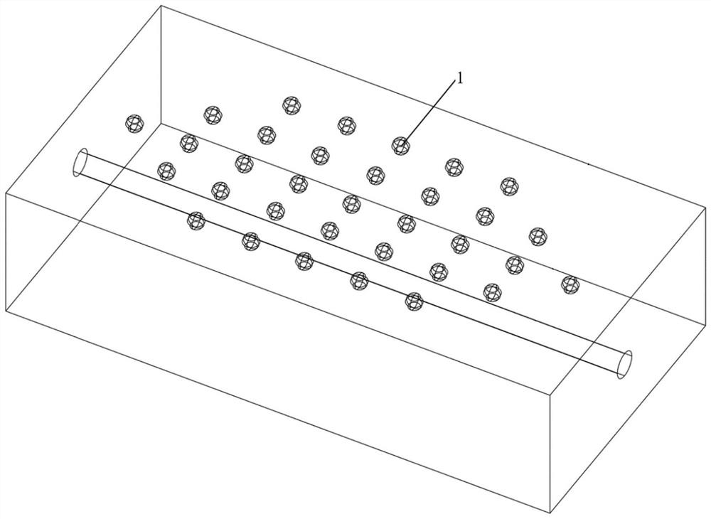
[0033] Step A: set 1 vibration sensor 1 in the area to be detected, and determine the coordinate system, record the vibration sensor 1 coordinates (x i ,y i ,z i );

[0034] The optional origin and direction of the coordinate system can be constructed, as long as the coordinates of all vibration sensors 1 are recorded in the same coordinate system, and the vibration sensors 1 can be directly laid on the ground of the area to be detected, or can be constructed underground at different heights From the point of view of convenience of work, it c...


PUM


Abstract

The present invention provides a method for locating leakage of gas pipelines based on vibration waves, comprising the following steps: Step A: set up multiple vibration sensors in the area to be detected, and record the coordinates of the vibration sensors; Step B: close the pipeline valve, then reopen it, and continue Collect the vibration wave signal; Step C: filter out the vibration wave signal with interference, and keep at least four valid signals; Step D: record the first arrival time t of the vibration wave detected by the vibration sensor i i ; Step E: Calculate the location coordinates of the pipeline leakage based on different leak location equations at the time. The advantages of the invention lie in that: the position of the leak point is determined by the vibration wave signals detected by multiple vibration sensors, the positioning accuracy is higher, the use is convenient, and it is suitable for various engineering needs; It reduces the influence of some discrete points on the calculation results, so that the results have good stability and robustness, and achieves high-precision positioning of gas pipeline leakage.

Description

technical field [0001] The invention relates to the technical field of gas leakage location, in particular to a vibration wave-based gas pipeline leak location method. Background technique [0002] The urban gas pipeline network is an important part of the basic engineering facility system that maintains the economic functions of the city and the region. Most of the urban long-distance pipeline networks in my country are underground, and there are problems such as monitoring, detection and leakage location difficulties. The gas leakage of deep buried pipelines is accurate. Positioning technology is the main means to ensure the safe operation and social stability of the pipeline network city. [0003] At present, according to the layout characteristics of the pipeline and the location characteristics of the pipeline, the pipeline leakage detection technology can be mainly divided into surface detection method, pipeline outer wall detection method and pipeline inner wall detect...

Claims


Application Information

Patent Timeline
Patent Type & Authority Patents(China)
IPC IPC(8): F17D1/02F17D5/02F17D5/06
CPCF17D1/02F17D5/02F17D5/06
Inventor 张平松李圣林邱实孙斌杨
Owner ANHUI UNIV OF SCI & TECH
Why Eureka
Try Eureka