Pneumatic current control electric heating system

A technology of air pressure control and electric heating, which is applied to fluid heaters, water heaters, lighting and heating equipment, etc. It can solve problems such as increased use costs, dangers, electric shocks, etc., and achieves reduced heat loss, improved efficiency, and energy density. high effect

Inactive Publication Date: 2017-11-03
SHIJIAZHUANG JIRUI ENERGY SAVING TECH
View PDF6 Cites 0 Cited by
  • Summary
  • Abstract
  • Description
  • Claims
  • Application Information

AI Technical Summary

Problems solved by technology

The electric heating tube is a fragile device and needs to be replaced frequently, which not only increases the cost of use, but also brings the risk of electric shock

Method used


Image

  • Pneumatic current control electric heating system

Examples


Embodiment 1

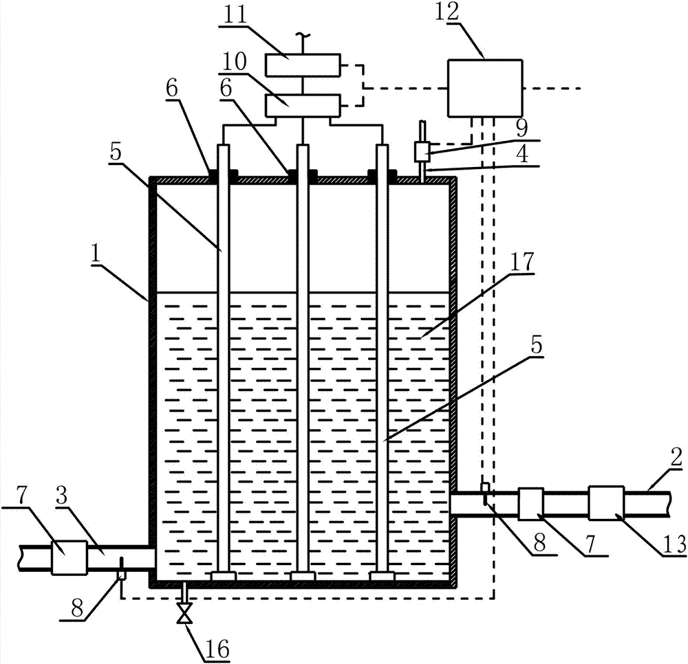
[0026] Such as figure 1 Shown is an electric heating system controlled by air pressure, which includes an electrothermal converter, and the electrothermal converter includes a sealed container 1, and the container 1 has a water inlet 2, a water outlet 3, and an air pressure control port 4; The container 1 is provided with at least one electrode 5 , the electrode 5 is inserted into the container 1 , an insulating sealing ring 6 is provided between the electrode 5 and the container 1 , and the terminal of the electrode 5 is outside the container 1 . The water inlet 2 is located at the upper part of the container 1, and the water outlet 3 is located at the lower part of the container 1. Both the water inlet 2 and the water outlet 3 are provided with an electric protection wall 7, and a temperature sensor 8 is installed therein. The air pressure control port 4 is connected to an air pressure controller 9 . The terminals of the electrodes 5 are connected to the AC power supply thr...

Embodiment 2

[0034] It is a heating application. When the indoor temperature is low, the heat exchange speed of the radiator is fast, and the water temperature in the water inlet 2 is low, so the controller 12 controls the AC contactor 11 to keep connected with the AC power supply through the relay. Make the electrode 5 in the working state to continuously heat the water in the container 1, and at the same time, the controller 12 controls the water pump 13 to work to increase the speed of the water flow and speed up the heat exchange to achieve the ideal indoor temperature. When the temperature in the water inlet 2 and the water outlet 3 both reach the set temperature value, the controller controls the AC contactor 11 to be disconnected from the AC power supply, so that the electrode 5 stops working, and the water pump 13 stops rotating at the same time to avoid energy loss , to maintain the ideal indoor temperature.

[0035] To sum up, the controller collects the water temperature signals...


PUM


Abstract

The invention relates to a pneumatic current control electric heating system. The pneumatic current control electric heating system comprises an electrothermal converter, wherein the electrothermal converter comprises a sealed container; at least one electrode is mounted on the container and inserted into the container; the electrodes and the container are sealed and fixed through an insulating material; wiring terminals of the electrodes are positioned outside the container and connected with an AC power supply; the container is provided with a water inlet and a water outlet each of which is provided with an electric protection wall; and the container is also provided with a pneumatic control port on which a pneumatic controller is mounted. The pneumatic current control electric heating system controls the water level through controlling the air pressure in the container, and the area of contact between water and the electrodes is controlled through the water level, further, the current is controlled, and the heating power is controlled.

Description

technical field [0001] The invention relates to the field of electric heating equipment, in particular to an electric heating system that directly heats water flow by using a current controlled by air pressure. Background technique [0002] In places without central heating, heating methods such as burning coal, burning wood, and burning oil are often used. Small-scale combustion devices often have low efficiency and high pollution. [0003] Electric energy can come from solar power, wind power, hydropower and other clean energy sources. Even for thermal power generation, its combustion efficiency and smoke treatment are far better than small-scale combustion devices. Today, when the power supply is relatively sufficient, the use of electric heating technology to replace burning coal and oil is of great significance to protecting the environment and has become the direction of development. [0004] The traditional way of making hot water with electric energy is to indirec...

Claims


Application Information

Patent Timeline
Patent Type & Authority Applications(China)
IPC IPC(8): F24H1/20F24H9/20
CPCF24H1/203F24H9/2021
Inventor 任金生徐亲民张传勇常和平
Owner SHIJIAZHUANG JIRUI ENERGY SAVING TECH
Why Eureka
Try Eureka