Device and method for leading out optical fiber grating sensor from composite axle tube

A technology of composite materials and optical fiber gratings, applied in the direction of measuring devices, instruments, measuring instrument components, etc., can solve the problems of difficult assembly of metal flanges, increased number of optical fiber outlets, and single point distribution direction, so as to improve performance and preparation quality, reduce Quantity, cost reduction effect

Active Publication Date: 2017-11-03
WUHAN UNIV OF TECH
View PDF7 Cites 3 Cited by
  • Summary
  • Abstract
  • Description
  • Claims
  • Application Information

AI Technical Summary

Problems solved by technology

[0004] However, at present, a lot of fiber grating sensor extraction methods are used to embed the grating between the layers of prepreg along the axial direction, and then the optical fiber is extracted from the end layer of the shaft tube. increase, the composite material shaft tube is easy to cause damage to the optical fiber when it is demoulded, and it is difficult to assemble with the metal flange, etc.

Method used


Image

  • Device and method for leading out optical fiber grating sensor from composite axle tube
  • Device and method for leading out optical fiber grating sensor from composite axle tube
  • Device and method for leading out optical fiber grating sensor from composite axle tube

Examples


Embodiment Construction

[0028] The present invention will be described in detail below in conjunction with the accompanying drawings and embodiments.

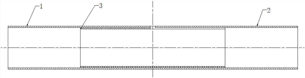
[0029] refer to Figure 1 ~ Figure 4 As shown, the device for drawing out the fiber grating sensor from the composite material shaft tube in one embodiment provided by the present invention, the first outer sleeve 1, the second outer sleeve 2 and the inner sleeve 3, one end of the inner sleeve 3 Set on the inner end of the first outer sleeve 1, the inner sleeve 3 is connected and fixed with the first outer sleeve 1, the other end of the inner sleeve 3 is set on the inner end of the second outer sleeve 2, the first outer sleeve The inner end of 1 is in contact with the inner end of the second outer sleeve 2;

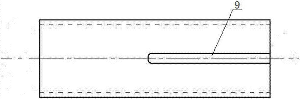
[0030] Wherein, the joint of the first outer sleeve 1 and the second outer sleeve 2 is provided with a through hole, and the through hole penetrates the inner sleeve 3 on one side of the inner sleeve wall, and the inner sleeve 3 is provided alon...


PUM


Abstract

The invention discloses a device and method for leading out an optical fiber grating sensor from a composite axle tube. The device includes a first outer sleeve, a second outer sleeve and an inner sleeve; one end of the inner sleeve is sleeved with the inner side end of the first outer sleeve; the inner sleeve is fixedly connected with the first outer sleeve; the other end of the inner sleeve is sleeved with the inner side end of the second outer sleeve; the inner side end of the first outer sleeve is in contact spliced connection with the inner side end of the second outer sleeve; a through hole is formed at the spliced joint of the first outer sleeve and the second outer sleeve; the through hole passes through the sleeve wall of one side of the inner sleeve; an open groove along the length direction of the sleeve wall of the inner sleeve is formed in the sleeve wall of the inner sleeve; and one end of the open groove is communicated with the through hole, and other end of the open groove extends to an end surface of one side of the inner sleeve, the second sleeve being located at the one side of the inner sleeve. With the device and method adopted, the problem that an optical fiber can be only led out from end surfaces of the axle tube can be solved; and optical gratings are distributed in an all-round multi-point manner between the laid layers of prepregs, and therefore, damage to the optical fiber and the composite axle tube in the separation process of the optical fiber and composite axle tube can be avoided, and the performance and preparation quality of the composite axle tube can be improved.

Description

technical field [0001] The invention relates to the technical field of optical fiber gratings, in particular to a device and method for leading out optical fiber grating sensors from a composite shaft tube. Background technique [0002] Due to its unique advantages, composite shaft tubes are widely used in large-scale high-end equipment such as helicopters, wind turbines, and heavy machine tools. However, due to the residual stress in the curing stage during the preparation of the prepreg to form the composite shaft tube, these residual stresses lead to defects in the product before service, which can easily cause potential hazards and seriously affect the mechanical properties of the product during service. Therefore, it is very important to monitor the curing process of the composite shaft tube. [0003] Fiber Bragg grating has the characteristics of small diameter, easy to embed, high temperature resistance, no electromagnetic interference, good electrical insulation, et...

Claims


Application Information

Patent Timeline
Patent Type & Authority Applications(China)
IPC IPC(8): G01D11/00
CPCG01D11/00
Inventor 丁国平曹皓张松超张锦光胡业发
Owner WUHAN UNIV OF TECH
Why Eureka
Try Eureka