A Method for Measuring Transverse Space Vibration of Wire Rope

A technology of vibration measurement and steel wire rope, which is applied in the direction of measuring devices, measuring ultrasonic/sonic/infrasonic waves, instruments, etc. It can solve the problems of difficult implementation, inability to guarantee measurement accuracy, adding laser sensors, etc., and achieve the effect of simple operation mode

Active Publication Date: 2019-11-08
HENAN UNIV OF SCI & TECH +1
View PDF6 Cites 0 Cited by
  • Summary
  • Abstract
  • Description
  • Claims
  • Application Information

AI Technical Summary

Problems solved by technology

In the prior art, the detection of the lateral vibration of the steel wire rope is mostly contact measurement, that is, the sensor is installed on the steel wire rope. Such measurement will bring additional interference. The Chinese patent application number 201410577225.3 is published to see a kind of axially moving rope lateral vibration measurement. Systematic method, which adopts the method of installing the laser displacement sensor on the top of the moving rope and running synchronously with the moving rope. The specific implementation is difficult and it is difficult to ensure whether the laser displacement sensor itself vibrates during operation, so that the accuracy of the measurement cannot be guaranteed. There is also a Chinese patent with application number 201510562399.7, which uses a light curtain laser displacement sensor to measure the lateral vibration of the steel wire rope. displacement along the axis of the cylinder), the number of laser sensors has to be increased, so the measurement cost will be greatly increased. At present, researchers have proposed a variety of numerical calculation methods to solve the vibration problem of steel wire ropes, but they have not proposed to verify these values. Correctness of Computational Algorithms for Solving Wire Rope Vibration Problems

Method used


Image

  • A Method for Measuring Transverse Space Vibration of Wire Rope
  • A Method for Measuring Transverse Space Vibration of Wire Rope
  • A Method for Measuring Transverse Space Vibration of Wire Rope

Examples


Embodiment Construction

[0023] The following will clearly and completely describe the technical solutions in the embodiments of the present invention with reference to the accompanying drawings in the embodiments of the present invention. Obviously, the described embodiments are only some, not all, embodiments of the present invention. Based on the embodiments of the present invention, all other embodiments obtained by persons of ordinary skill in the art without making creative efforts belong to the protection scope of the present invention.

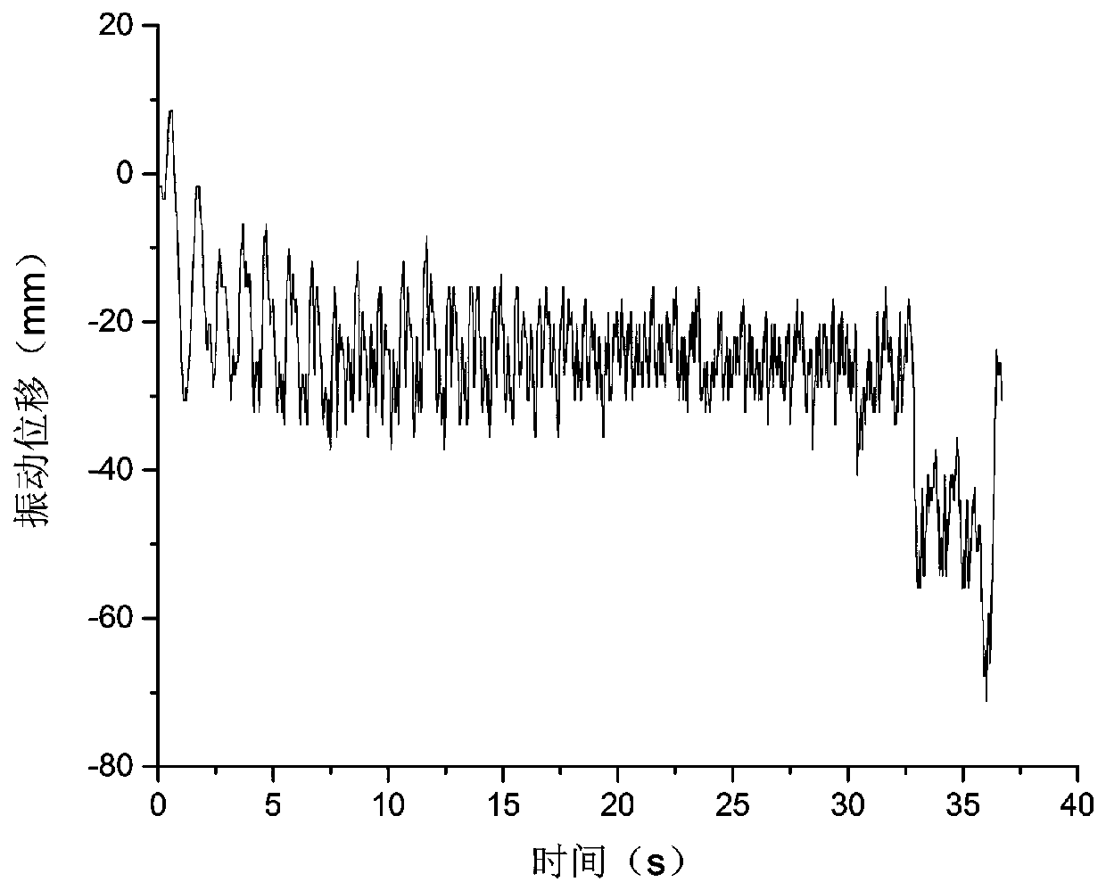
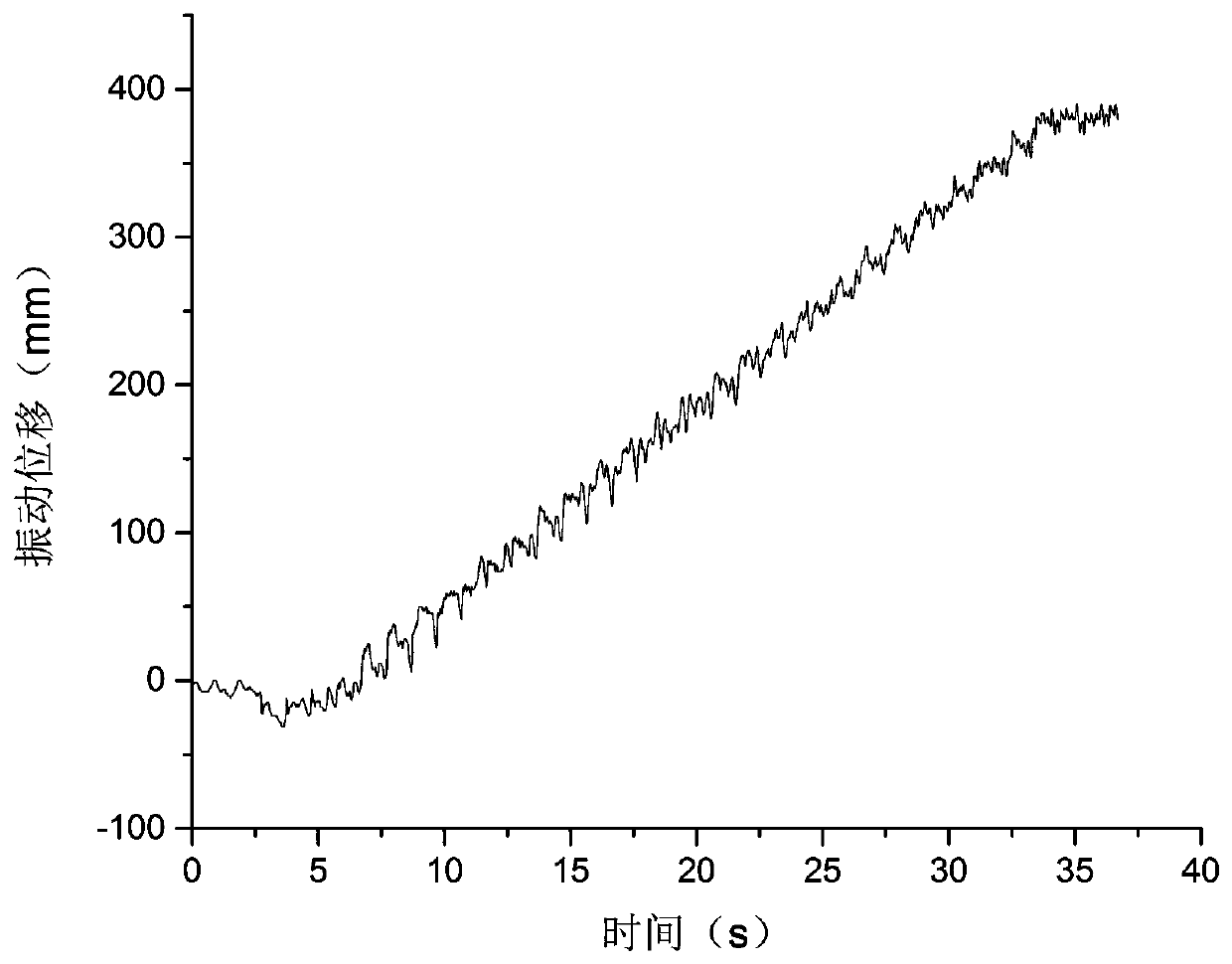
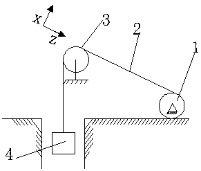
[0024] see Figure 1-4 Shown: Taking the horizontal space vibration detection of the steel wire rope between the winding hoist drum and the sky wheel as an example, as shown in Figure 4 As shown, 1 is the hoist drum, 2 is the wire rope between the hoist drum and the hoisting sky wheel, 3 is the sky wheel, and 4 is the lifting load, so what needs to be detected is the distance between the hoist drum 1 and the sky wheel 3. Horizontal spatial vibration, establi...


PUM


Abstract

The invention discloses a steel wire rope transverse space vibration measurement method. A steel wire rope vibration image is acquired through two mutually-vertical high-speed cameras, the same areas are selected on the image through a computer steel wire rope vibration detection program, the selected areas are subjected to binarization processing to obtain a 01 matrix for images in the areas, the pixel coordinate value of the steel wire rope centroid in a width direction is calculated and obtained, the actual displacement of the steel wire rope centroid in the selected area in a background screen plane is solved according to the scale of the image and the background and the pixel coordinates in the width direction, steel wire rope centroid vibration trajectories in multiple different areas are selected in a time period, and through connecting coordinates of space positions of the steel wire rope centroid at the same moment in the selected different areas, the space vibration shape of the steel wire rope at a t moment is obtained. In a non-contact measurement mode, the terminal is measured statically, the detection range is adjustable and large, and steel wire rope transverse space vibration measurement on all systems with the steel wire rope as a transmission mode can be met.

Description

technical field [0001] The invention relates to a method for measuring the lateral spatial vibration of a steel wire rope, in particular to a method for measuring the lateral spatial vibration of a steel wire rope based on high-speed camera image acquisition and computer image processing principles. Background technique [0002] As the key equipment for mine transportation, the mine hoist is responsible for the lifting of coal and ore, the lifting of personnel, and the transportation of materials and equipment. It is an important equipment connecting the underground and the ground. As the main transmission mode of the hoisting system, the wire rope’s lateral vibration directly affects the stability of the hoisting process and the fatigue life of the wire rope. When the wire rope’s lateral vibration displacement is too large, it may cause contact interference with the surrounding objects, which seriously threatens the safety of the hoisting process. safety. [0003] In the p...

Claims


Application Information

Patent Timeline
Patent Type & Authority Patents(China)
IPC IPC(8): G01H9/00
CPCG01H9/00
Inventor 李济顺李东亮马喜强薛玉君王晓杨芳李伦马伟邹声勇
Owner HENAN UNIV OF SCI & TECH
Why Eureka
Try Eureka