In-situ chip fixing structure of transmission electron microscope sample holder

An electron microscope and a fixed structure technology, applied in the direction of material analysis using radiation, material analysis using wave/particle radiation, and measuring devices, can solve the problems of in-situ chips that are difficult to fix, inconvenient to use, and high in use cost, and achieve Improve the effect of time cost and economic cost

Active Publication Date: 2017-11-03
NINGBO INST OF MATERIALS TECH & ENG CHINESE ACADEMY OF SCI
View PDF17 Cites 8 Cited by
  • Summary
  • Abstract
  • Description
  • Claims
  • Application Information

AI Technical Summary

Problems solved by technology

[0005] The present invention is mainly aimed at the problem that the in-situ chip is difficult to fix due to the small electrode volume and the small electrode spacing in the in-situ chip, and the entire sample rod of the transmission electron microscope needs to be replaced when the in-situ chip is replaced, resulting in inconvenient use and high use cost In order to solve the problem, an in-situ chip fixing structure for the transmission electron microscope sample rod is provided, which can conveniently fix and install the in-situ chip. At the same time, the head of the sample rod can be disassembled and replaced at any time, and there is no need to replace the entire transmission electron microscope sample rod.

Method used


Image

  • In-situ chip fixing structure of transmission electron microscope sample holder
  • In-situ chip fixing structure of transmission electron microscope sample holder
  • In-situ chip fixing structure of transmission electron microscope sample holder

Examples


Embodiment Construction

[0021] Embodiments of the present invention will be described in further detail below in conjunction with the accompanying drawings.

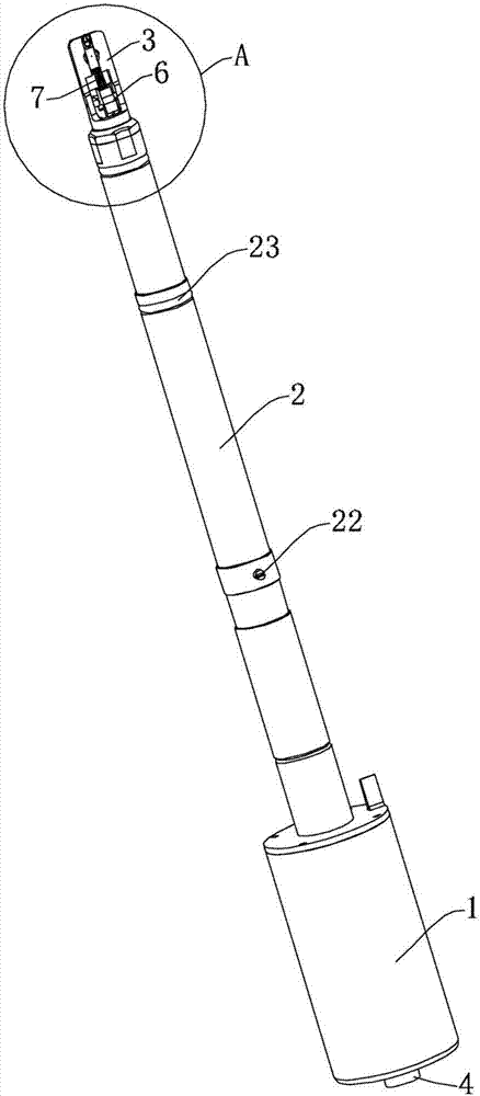
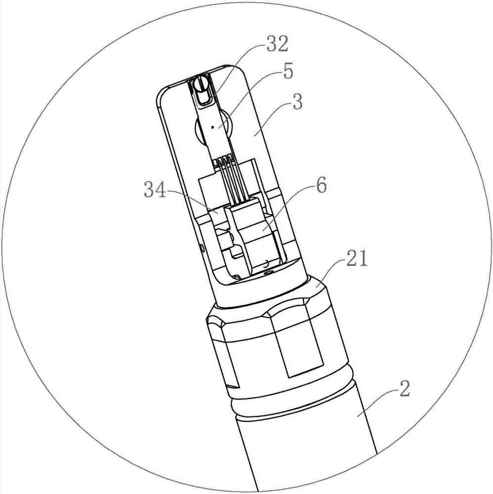
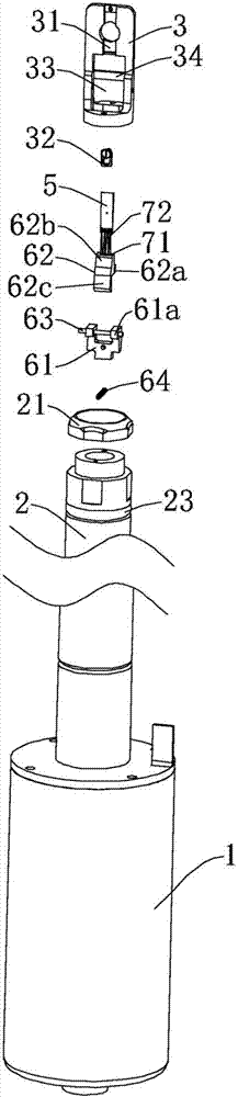
[0022] Figure 1 to Figure 3 Shown is the structural representation of the present invention.

[0023] The reference signs are: hand handle 1, sample rod main body 2, threaded end cap 21, guide pin 22, sealing ring 23, sample rod head 3, fixing groove 31, non-magnetic pressing piece 32, installation groove 33, Limiting plate 34, vacuum electrical connector 4, in-situ chip 5, conductive pin mounting seat 6, rotating base 61, lug mounting part 61a, rotating top cover 62, connecting part 62a, mounting part 62b, pressing part 62c, rotating shaft 63, non-magnetic spring 64, non-magnetic conductive needle 7, needle tube 71, needle point 72.

[0024] Such as figure 1 As shown, an in-situ chip fixing structure for a transmission electron microscope sample rod of the present invention includes a handle 1 , a sample rod body 2 , a sample rod head 3 an...


PUM


Abstract

The invention discloses an in-situ chip fixing structure of a transmission electron microscope sample holder. The in-situ chip fixing structure comprises a handheld handle, a sample holder main body, a sample holder head and a vacuum electrical connector, wherein a fixing slot for installing an in-situ chip is formed in the front part of the sample holder head; a non-magnetic pressure plate for fixing the in-situ chip is arranged at the front end part of the fixing slot; a mounting groove is formed in the middle part of the sample holder head; a rotational conductive needle mounting base is arranged in the mounting groove; a non-magnetic conductive needle connected with the vacuum electrical connector is arranged on the conductive needle mounting base; the end part of the non-magnetic conductive needle is connected with an electric contact on the in-situ chip; the tail end of the sample holder head is detachably connected with the sample holder main body through threads; when the in-situ chips with different types are used, the sample holder heads with different sizes only need to be changed, and the whole sample holder does not need to be changed, so that time cost and economic cost of experiments are greatly reduced.

Description

technical field [0001] The invention belongs to the technical field of in-situ testing of a transmission electron microscope, and in particular relates to an in-situ chip fixing structure of a sample rod of a transmission electron microscope. Background technique [0002] The transmission electron microscope uses the ultra-short wavelength of the electron wave to display the internal microstructure of the object, and can study the morphology, structure, composition and electronic state of the material at the atomic scale. An extremely important research tool in various fields. As one of the important components of the transmission electron microscope, the sample rod plays the role of carrying the sample on the one hand, and on the other hand, it can introduce force, electricity, heat, light, etc. on the sample to realize the in-situ observation of the transmitted sample. The transmission electron microscope in-situ test is to realize the real-time observation of the specifi...

Claims


Application Information

Patent Timeline
Patent Type & Authority Applications(China)
IPC IPC(8): G01N23/04
CPCG01N23/04G01N2223/30G01N2223/03
Inventor 田悦夏卫星裴科吴博杜娟张健刘平
Owner NINGBO INST OF MATERIALS TECH & ENG CHINESE ACADEMY OF SCI
Why Eureka
Try Eureka