Video processing-based illumination-adaptive multi-vehicle automatic speed measurement method

A video processing and adaptive technology, applied in the field of multi-vehicle automatic speed measurement, can solve the problems of high installation accuracy and cumbersome calibration

Active Publication Date: 2017-11-03
HARBIN INST OF TECH
View PDF7 Cites 12 Cited by
  • Summary
  • Abstract
  • Description
  • Claims
  • Application Information

AI Technical Summary

Problems solved by technology

[0004] The present invention aims to solve the problems of cumbersome calibration and high requirements for ins

Method used


Image

  • Video processing-based illumination-adaptive multi-vehicle automatic speed measurement method
  • Video processing-based illumination-adaptive multi-vehicle automatic speed measurement method
  • Video processing-based illumination-adaptive multi-vehicle automatic speed measurement method

Examples


specific Embodiment approach 1

[0066] Specific implementation mode one: combine figure 1 To describe this embodiment,

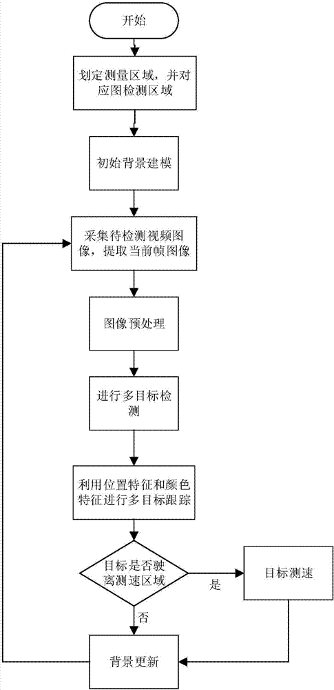
[0067] A multi-vehicle automatic speed measurement method with illumination adaptability based on video processing, comprising the following steps:

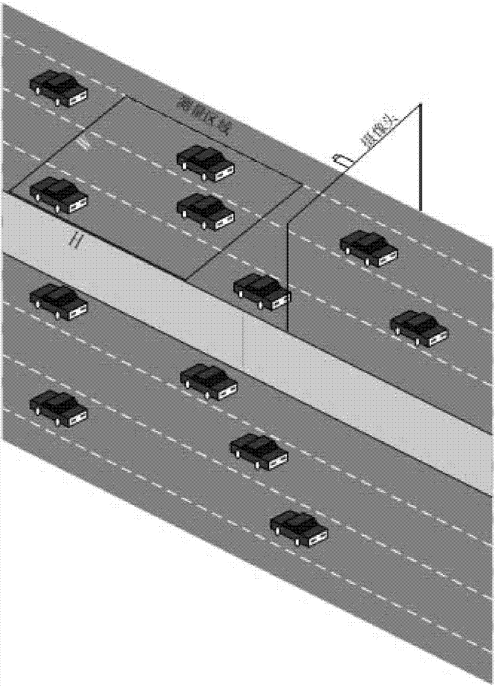
[0068] Step 1. Fix the camera above the one-way lane. On the one-way lane corresponding to the camera, artificially delineate the speed measurement start line, speed measurement end line and the left and right boundary lines of the lane. The area enclosed by the boundary line is defined as the measurement area (W×H), with a width of W meters and a length of H meters, such as figure 2 shown; and the corresponding area of ​​the measurement area (W×H) in the image obtained by the camera is recorded as the image detection area (w×h), with a width of w pixels and a length of h pixels, and the corresponding speed measurement starting point in the image is obtained The line corresponding to the starting line, the line corresponding to the end lin...

specific Embodiment approach 2

[0077] Specific implementation mode two: combination image 3 To describe this embodiment,

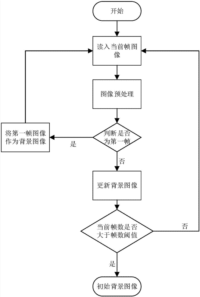
[0078] The process of establishing the initial background image of the captured image described in step 2 of this embodiment includes the following steps:

[0079] For the video image captured by the camera, preprocess the current frame image; then create a background image:

[0080] If the current frame is the first frame of the video image, the first frame image I obtained after preprocessing 1 (i, j) as the first frame background image B 1 (i, j); otherwise, according to the current frame image I obtained after preprocessing current (i, j) and the previous frame background image B of the current frame current-1 (i,j), calculate the background image B of the current frame according to the following formula current (i, j),

[0081] B current (i, j) = αI current (i,j)+(1-α)B current-1 (i,j)

[0082] In the formula, B current (i, j) is the background image of the current fram...

specific Embodiment approach 3

[0086] The process of preprocessing the current frame image described in step 2 of this embodiment includes the following steps:

[0087] If the brightness of the current frame image is higher than the enhanced brightness threshold T brightness , then convert the color image into a grayscale image, and then perform Gaussian smoothing filtering on the obtained grayscale image (generally using a 3*3 rectangular template) to obtain the preprocessed image I current (i, j), where i, j are image pixel coordinates; if the image brightness is lower than or equal to the enhanced brightness threshold T brightnessWhen using the scheme described in "Fast Low-Illumination Image Enhancement Method Based on Improved Dark Channel Prior" (Patent No.: ZL20130325849.1) to enhance the color image, the enhanced color image is obtained, and then the enhanced color image is converted into Grayscale image, and finally Gaussian smoothing filtering is performed on the obtained grayscale image (general...


PUM


Abstract

The invention relates to a vehicle automatic speed measurement method, in particular, a video processing-based illumination-adaptive multi-vehicle automatic speed measurement method. The invention aims to solve the problems of complicated calibration and high requirements for installation accuracy of an existing method for performing vehicle speed measurement on the basis of binocular stereo vision. According to the method of the invention, a camera is used to collect video images, an initial background image is built, and a speed measurement region is defined; the camera is used to collect video images to be detected, a current frame image is extracted from the video images to be detected obtained by the camera, and is preprocessed; and multi-target detection is performed, the position features and color features of vehicles are obtained, multi-target tracking is performed on the basis of vehicle position features and color features in a corresponding image detection region of a last frame image as well as corresponding vehicle position features and color features in the current frame image, and whether target vehicles drive out from the speed measurement region is judged, and the speed of the targets is measured. The method of the invention is suitable for multi-vehicle automatic speed measurement.

Description

technical field [0001] The invention relates to a multi-vehicle automatic speed measurement method. Background technique [0002] With the increasing number of motor vehicles, traffic management needs more efficient and feasible methods to maintain traffic order. Among the existing vehicle speed measurement systems, radar speed measurement, laser speed measurement, and coil speed measurement are more popular, and the technology is relatively mature; however, radar speed measurement is expensive and easy to be counter-detected by electronic dogs, and radar speed measurement does not provide multi-channel support. That is to say, a radar speedometer can usually only measure the speed of a single vehicle, resulting in low radar speed measurement efficiency; the induction coil speed measurement can only be used for fixed point monitoring, the measurement repeatability is low, the data volatility is large, and the installation of the induction coil will cause There is some damag...

Claims


Application Information

Patent Timeline
IPC IPC(8): G01P3/38G06K9/00
CPCG01P3/38G06V20/42
Inventor 遆晓光张浩鑫
Owner HARBIN INST OF TECH
Why Eureka
Try Eureka