
Rotary oil-spray-coating drying device for bearing machining

A bearing processing and drying device technology, which is applied to spray devices, devices for applying liquid to surfaces, coatings, etc., can solve the problem of increasing the cost of oil spray devices and manufacturing costs, and cannot meet the requirements of large-scale bearing oil spray and lubrication. The problem of large amount of oil waste, etc., achieves the effect of novel design, strong practicability, and reduced fuel injection cost

Inactive Publication Date: 2017-11-07
孙小荣
View PDF0 Cites 30 Cited by
  • Summary
  • Abstract
  • Description
  • Claims
  • Application Information

AI Technical Summary

Problems solved by technology

However, this spray oiling method uses oil immersion or oil spraying to carry out oiling treatment. When oil immersion treatment is adopted, the waste of lubricating oil is very large, and the efficiency is also very low. When spraying oil, although the above-mentioned waste of lubricating oil can be avoided, the current oil spraying method is to place the bearing on the horizontal conveyor belt and spray oil while conveying, which virtually increases the occupation of the entire oil spraying device. The land cost and manufacturing cost also cannot meet the needs of large-scale bearing oil injection, and the practicability is poor

Method used


Image

  • Rotary oil-spray-coating drying device for bearing machining
  • Rotary oil-spray-coating drying device for bearing machining
  • Rotary oil-spray-coating drying device for bearing machining

Examples


Embodiment Construction

[0023] It should be noted that, in the case of no conflict, the embodiments of the present invention and the features in the embodiments can be combined with each other.

[0024] In describing the present invention, it should be understood that the terms "center", "longitudinal", "transverse", "upper", "lower", "front", "rear", "left", "right", " The orientations or positional relationships indicated by "vertical", "horizontal", "top", "bottom", "inner" and "outer" are based on the orientations or positional relationships shown in the drawings, and are only for the convenience of describing the present invention and Simplified descriptions, rather than indicating or implying that the device or element referred to must have a particular orientation, be constructed and operate in a particular orientation, and thus should not be construed as limiting the invention. In addition, the terms "first", "second", etc. are used for descriptive purposes only, and should not be understood ...


PUM


Abstract

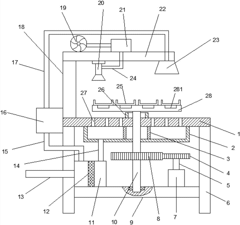
The invention discloses a rotary oil-spray-coating drying device for bearing machining. The rotary oil-spray-coating drying device for bearing machining comprises a supporting base; support legs are connected with the two sides of the lower end of the supporting base, a reinforcing plate is connected between the lower ends of the supporting legs, a driving motor is connected with the right side of the upper end of the reinforcing plate, and a driving shaft is connected with the upper end of the driving motor; a driving gear is connected with the upper end of the driving shaft, gear teeth groups are evenly connected with the outer side of the driving gear, and a driven gear is engaged with the left end of the driving gear; a rotating shaft is connected to the middle of the driven gear, a worktable is connected with the upper end of the rotating shaft, and an oil storing box is connected with the left side of the upper end of the reinforcing plate; an oil outlet pipe is connected with the left side of the upper end of the oil storing box, an oil leading pump is connected with the upper end of the oil outlet pipe, and an oil spraying pipe is connected with the upper end of the oil leading pump; an oil returning trough is connected with the middle of the lower end of the supporting base, a sealing plate is arranged in the oil returning trough, and an oil returning pipe is connected with the lower end of the oil returning trough. According to the rotary oil-spray-coating drying device for bearing machining, rotary oil-spray-coating for a bearing is realized, oil spraying cost is reduced, and requirements for large-scale bearing oil-spray-coating machining are met.

Description

technical field [0001] The invention relates to the technical field of bearing processing equipment, in particular to a spray oiling drying device for rotary bearing processing. Background technique [0002] Bearings are an important part of contemporary mechanical equipment. Its main function is to support the mechanical rotating body, reduce the friction coefficient during its movement, and ensure its rotation accuracy. According to the different friction properties of moving elements, bearings can be divided into two categories: rolling bearings and sliding bearings. Among them, the rolling bearing has been standardized and serialized, but compared with the sliding bearing, its radial dimension, vibration and noise are larger, and the price is also higher. Rolling bearings are generally composed of four parts: outer ring, inner ring, rolling element and cage. Strictly speaking, they are composed of six parts: outer ring, inner ring, rolling element, cage, seal, and lubr...

Claims


Application Information

Patent Timeline
Patent Type & Authority Applications(China)
IPC IPC(8): B05B13/02B05B13/04B05B15/12
CPCB05B13/0228B05B13/0292B05B13/0421B05B14/40B05B16/20
Inventor 孙小荣
Owner 孙小荣
Learn More