
Automated punch press

A punch and guide rail technology, applied in the field of automatic forming and feeding, can solve the problems of high labor intensity, cumbersome operation, low degree of automation, etc., and achieve the effect of reducing labor intensity

Pending Publication Date: 2017-11-07
浙江东雄机床有限公司
View PDF5 Cites 18 Cited by
  • Summary
  • Abstract
  • Description
  • Claims
  • Application Information

AI Technical Summary

Problems solved by technology

In industrial production, compared with traditional mechanical processing, stamping process has the advantages of saving materials and energy, high efficiency, low technical requirements for operators, and through various mold applications, it can make products that cannot be achieved by mechanical processing. , at present, in the production process of domestic stamping forming, the degree of automation is not high, because in the production process of domestic stamping forming devices, the manufacturer of the punching machine and the manufacturer of the mold are not the same manufacturer, and the design of automation is For other manufacturers, different products require different feeding and discharging mechanisms. At the same time, different product shapes and product characteristics also need to consider different positioning mechanisms. The degree of automation of the molding device has not been high.
But the current situation is that with the gradual increase in labor costs, the proportion of wage costs in product costs is getting higher and higher. In order to improve the competitiveness of products, enterprises must improve the efficiency of feeding materials, and the labor intensity of operators is high. There are many shortcomings such as high risk of misoperation, cumbersome operation, and low work efficiency. Therefore, an automatic punching machine is proposed

Method used


Image

  • Automated punch press
  • Automated punch press
  • Automated punch press

Examples


Embodiment Construction

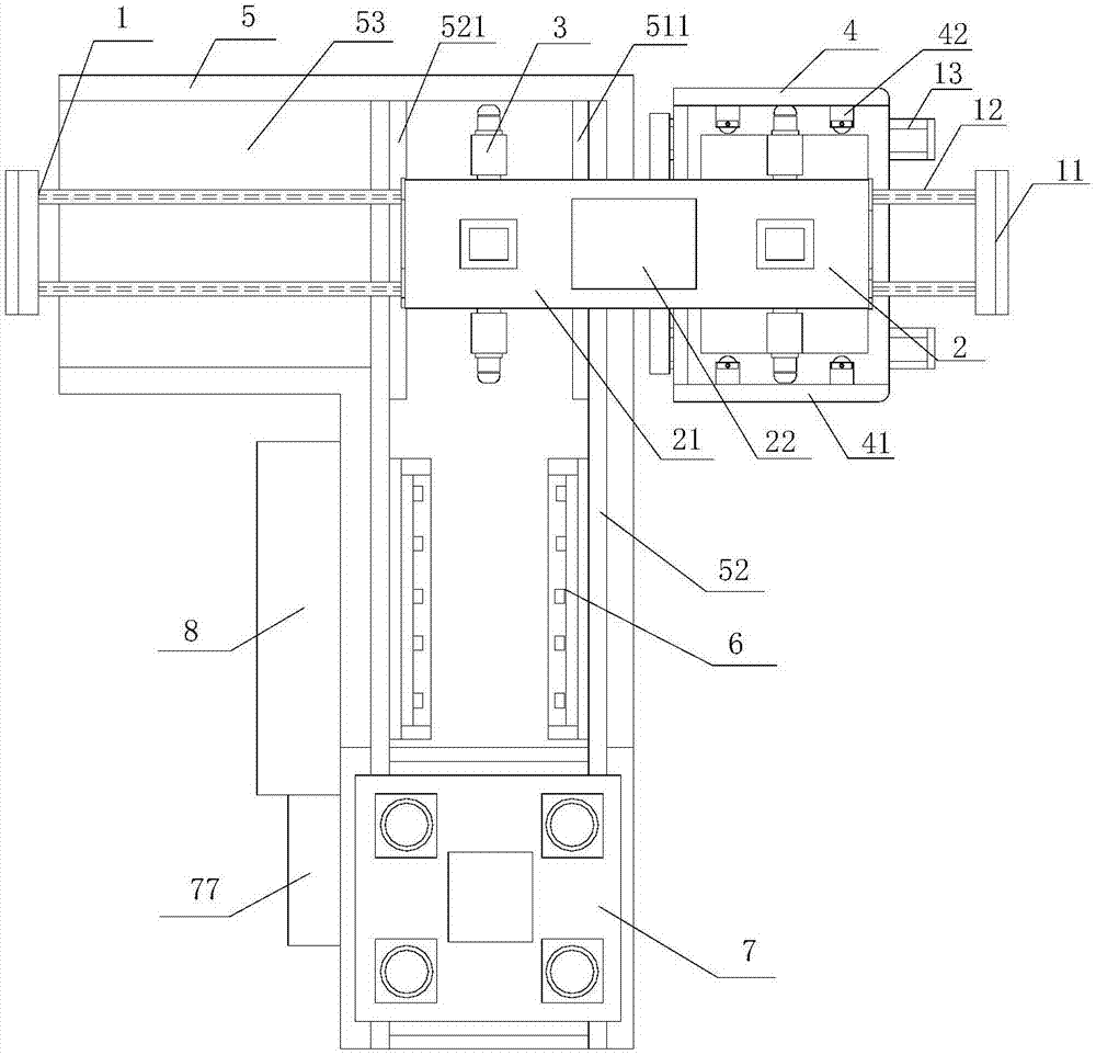
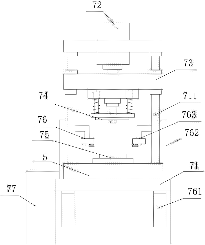
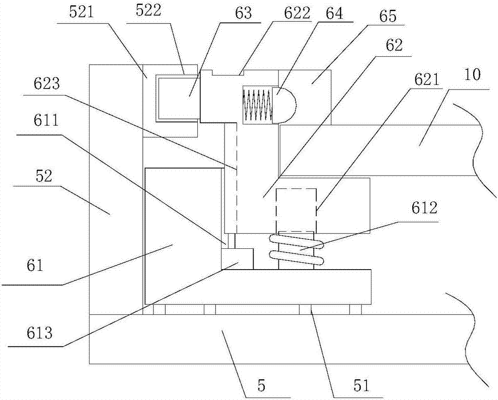
[0020] refer to Figure 1 to Figure 6An automatic punching machine of the present invention comprises a walking support frame 1, a feeding walking seat 2, a jaw feeding mechanism 3, a storage trolley 4, a workbench 5, a feeding mechanism 6, a punch device 7 and a control system 8, the walking The support frame 1 is provided with two walking guide rails 12, and the feeding walking seat 2 is installed on the walking guide rail 12, and the two ends of the feeding walking seat 2 are symmetrically equipped with claw feeding mechanisms 3, and the walking guide rails 12 A workbench 5 is provided below, and a storage trolley 4 is provided on one side of the workbench 5, and the storage trolley 4 cooperates with the claw feeding mechanism 3, and a first slide is provided above the workbench 5. Rail 51, one end of the first slide rail 51 is located below the walking guide rail 12, the other end of the first slide rail 51 is located below the punch device 7, and the feeding mechanism 6 i...


PUM


Abstract

The invention provides an automated punch press which comprises a travelling support, a feeding travelling seat, clamping jaw feeding mechanisms, a storing trolley, a workbench, a feeding mechanism, a punch press unit and a control system. Two travelling guiding rails are arranged on the travelling support, and the feeding travelling seat is installed on the travelling guiding rails. The clamping jaw feeding mechanisms are symmetrically installed at the two ends of the sending travelling seat, and the storing trolley is arranged on one side of the workbench. The storing trolley is matched with the clamping jaw feeding mechanisms, and a first sliding rail is arranged above the workbench. The feeding sliding seat is arranged on the feeding mechanism and is installed on the first sliding rail, and a positioning installation seat is arranged on the feeding sliding seat. A locking mechanism is arranged on the punch press unit and is matched with the positioning installation seat, the clamping jaw feeding mechanisms can act in a reciprocating mode on three stations, and automatic feeding and discharging are achieved; and plates are positioned and locked through the locking mechanism, and the labor intensity of an operator is relieved.

Description

【Technical field】 [0001] The invention relates to the technical field of automatic forming and feeding, in particular to an automatic punching machine. 【Background technique】 [0002] The punch press is a stamping press. In industrial production, the stamping process has the advantages of saving materials and energy compared with traditional mechanical processing, high efficiency, low technical requirements for operators, and through various mold applications, it can make products that cannot be achieved by mechanical processing. , at present, in the production process of domestic stamping forming, the degree of automation is not high, because in the process of domestic stamping forming device production, the manufacturer of the punching machine and the manufacturer of the mold are not the same manufacturer, and the design of automation is For other manufacturers, different products require different feeding and discharging mechanisms. At the same time, different product sh...

Claims


Application Information

Patent Timeline
IPC IPC(8): B21D22/02B21D43/11B21D43/00B21D43/18B21D43/02B21D45/06
CPCB21D22/02B21D43/003B21D43/026B21D43/027B21D43/11B21D43/18B21D45/06Y02P70/10
Inventor 王育文钱志勇袁磊王春风成荣栋俞海峰徐剑飞俞中杰张建东袁鑫
Owner 浙江东雄机床有限公司
Features
  • Generate Ideas
  • Intellectual Property
  • Life Sciences
  • Materials
  • Tech Scout
  • Unparalleled Data Quality
  • Higher Quality Content
  • 60% Fewer Hallucinations
Learn More