
A drawing die composed of cemented carbide and gray iron

A cemented carbide, drawing die technology, applied in forming tools, manufacturing tools, metal processing equipment, etc., can solve problems such as high cost and long machining time

Active Publication Date: 2020-01-03
湖南湖大三佳车辆技术装备有限公司
View PDF8 Cites 0 Cited by
  • Summary
  • Abstract
  • Description
  • Claims
  • Application Information

AI Technical Summary

Problems solved by technology

This is costly and takes a long time to machine

Method used


Image

  • A drawing die composed of cemented carbide and gray iron
  • A drawing die composed of cemented carbide and gray iron
  • A drawing die composed of cemented carbide and gray iron

Examples


Embodiment Construction

[0024] The present invention will be described in detail below with reference to the accompanying drawings. The description in this part is only exemplary and explanatory, and should not have any limiting effect on the protection scope of the present invention. In addition, those skilled in the art can make corresponding combinations of features in the embodiments in this document and in different embodiments according to the descriptions in this document.

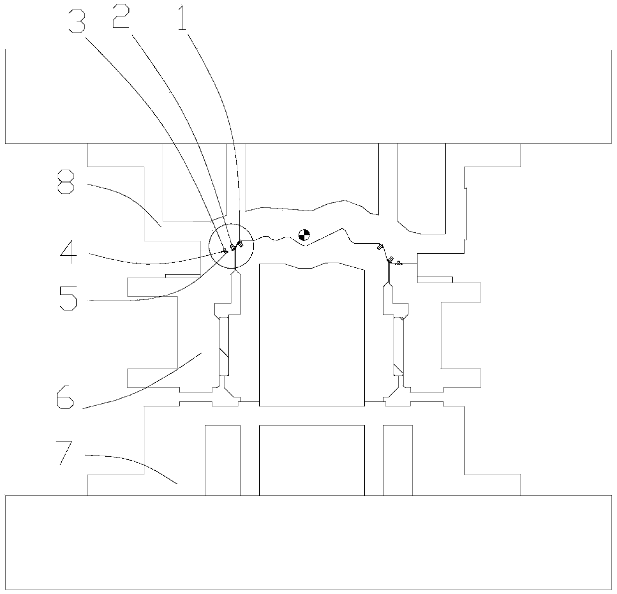
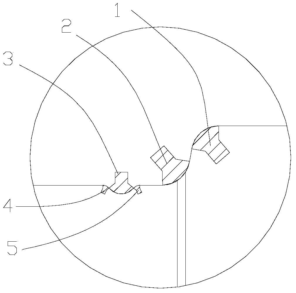
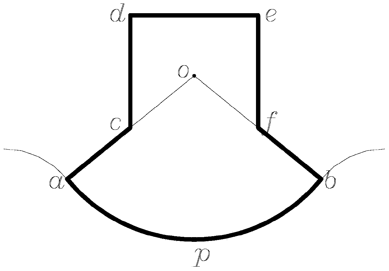
[0025] Embodiments of the present invention are as follows, see Figure 1 to Figure 3 As shown, a drawing die composed of cemented carbide and gray iron includes an upper mold body 8 and a lower mold body 7 oppositely arranged, wherein the upper mold body 8 and / or the lower mold body 7 are provided with convex A mold and / or a concave mold, the rounded corners of the convex mold and / or the concave mold are provided with hard alloy parts. Specifically, as figure 1 and figure 2 As shown, the convex mold insert 1 is arrang...


PUM


Abstract

The invention provides a drawing die made from a hard alloy and gray iron. The drawing die comprises an upper die body and a lower die body which are oppositely arranged; a male die and / or a female die are / is arranged on the upper die body and / or the lower die body; and a hard alloy part is arranged at a fillet of the male die and / or the female die. Therefore, the hard alloy part is arranged at the fillet of the male die and / or the female die, so that a requirement on the performance of a material of a male die and / or the female die body is lowered, for example, the male die and / or the female die body adopts the gray iron and the like; therefore, the material use cost of the drawing die is reduced, and the machining and assembling time is shortened; and the machining efficiency of the die is improved.

Description

technical field [0001] The invention relates to the field of molds, in particular to a drawing mold composed of hard alloy and gray iron. Background technique [0002] Stamping die is a special process equipment for processing metal or non-metallic materials into parts or semi-finished products in cold stamping processing. The mold installed on the press is used to apply pressure to the material to cause separation or plastic deformation, so as to obtain A method of press-working the desired part. [0003] According to the nature of the process, the stamping die can be divided into: (1) Drawing die, which is a die that obtains a stable spatial shape through plastic deformation of the flat blank through the joint action of the punch, blank holder, and die. (2) Trimming mold, a mold that separates materials along closed or open contours. (3) The forming mold is a mold that directly copies the rough or semi-finished workpiece according to the shape of the convex and concave m...

Claims


Application Information

Patent Timeline
Patent Type & Authority Patents(China)
IPC IPC(8): B21D37/01
CPCB21D37/01
Inventor 钟志华刘林峰
Owner 湖南湖大三佳车辆技术装备有限公司
Learn More