A method for processing the lock opening of the last rotor blade with threads

A processing method and rotor technology, applied in the field of steam turbines, can solve problems such as long processing time, difficult processing, and complex structure, and achieve the effects of simple operation, reduced processing cost, and improved processing efficiency

Active Publication Date: 2019-02-26
HARBIN TURBINE +1
View PDF6 Cites 0 Cited by
  • Summary
  • Abstract
  • Description
  • Claims
  • Application Information

AI Technical Summary

Problems solved by technology

[0004] The purpose of the present invention is to solve the problem that the existing threaded rotor final blade lock mouth has a rhombus-shaped installation window, and at the same time, two half-section threads need to be processed on the locking blade window, and the structure is complex, so there is difficulty in processing. Large size, low precision, long processing time, and low efficiency, and then provide a threaded rotor blade lock processing method

Method used


Image

  • A method for processing the lock opening of the last rotor blade with threads
  • A method for processing the lock opening of the last rotor blade with threads
  • A method for processing the lock opening of the last rotor blade with threads

Examples


specific Embodiment approach 1

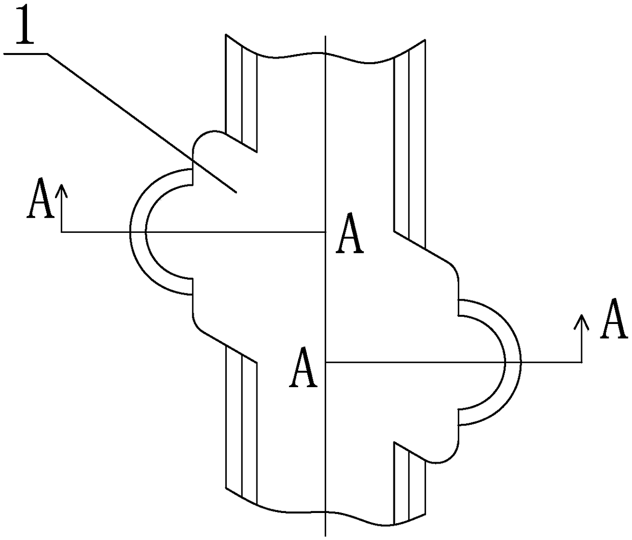
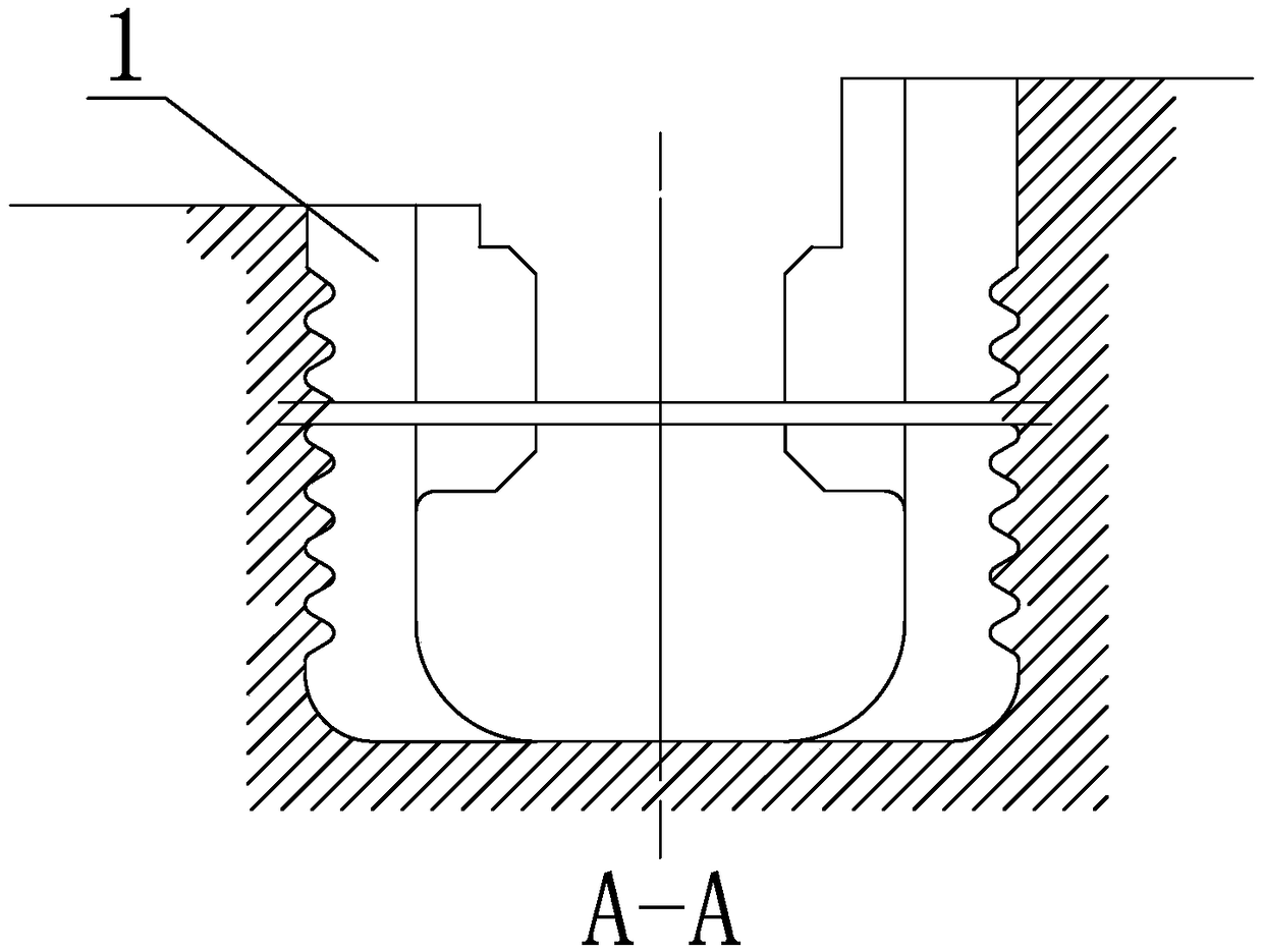
[0035] Specific implementation mode one: combine Figure 1 to Figure 6 Describe this embodiment, a method for processing a threaded rotor end blade lock in this embodiment, the processing method includes the following steps,

[0036] Step 1. Install and align the rotor:

[0037] Install the rotor on the boring machine through the bracket, align the position of the rotor T-shaped blade root and blade 1 lock with the main shaft of the boring machine, and align the rotor at the same time;

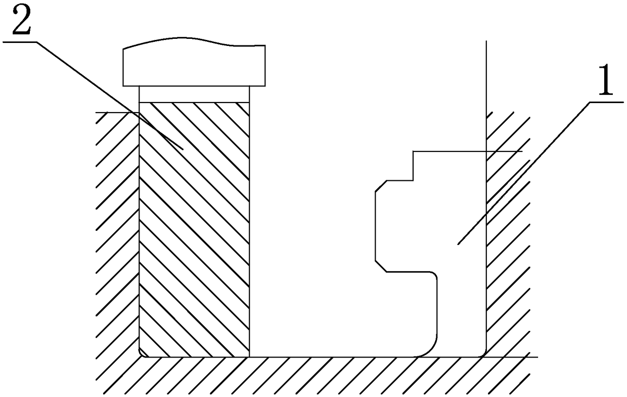
[0038] Step 2. Use the first end mill 2 to roughly machine the lock mouth profile of the rotor T-shaped blade root and blade 1:

[0039] Install the first end mill 2 on the boring machine, perform tool setting on the first end mill 2 according to the lock shape of the rotor T-shaped blade root and end blade 1, use the program according to the zero point of the tool that has been aligned, and pass the first vertical The milling cutter 2 rough-machines the lock mouth profile of the rotor T-sha...

specific Embodiment approach 2

[0048] Specific implementation mode two: combination image 3 and Figure 4To describe this embodiment, the rotational speed of the first end mill 2 in step 2 of this embodiment is 300 r / min; the cutting amount is 0.08 mm / r. With this arrangement, the first end mill 2 is used to roughly machine the profile of the rotor T-shaped blade root and terminal blade 1 lock, which ensures the machining accuracy of the rotor T-shaped blade root and terminal blade 1 lock profile, shortens the processing time, and effectively improves the The machining efficiency of the final blade lock. Other compositions and connections are the same as in the first embodiment.

specific Embodiment approach 3

[0049] Specific implementation mode three: combination Figure 4 The present embodiment will be described. In step 3 of the present embodiment, the rotational speed of the second end mill is 310 r / min, and the cutting amount is 0.09 mm / r. With this setting, the second end mill is used to finish machining the rotor T-shaped blade root and final blade 1 lock, which ensures the machining accuracy of the rotor T-shaped blade root and final blade 1 lock, shortens the processing time, and effectively improves the lock of the final blade. Mouth processing efficiency. Other compositions and connections are the same as those in Embodiment 1 or Embodiment 2.


PUM


Abstract

The invention provides a machining method of a rotor root blade locking window provided with threads, and relates to the field of steam turbines. By adoption of the machining method, the problems that according to an existing rotor root blade locking window provided with threads, due to the fact that a mounting window is a rhombic window, two parts of semi-sectioned threads need to be machined on the blade locking window, and the structure is complex; and in the machining process, the machining difficulty is high, the precision is low, the machining time is long, and the efficiency is low are solved. The machining method of the rotor root blade locking window provided with the threads comprises the steps that firstly, a rotor is mounted and aligned; secondly, the contour of the T-shaped root blade locking window of the rotor is roughly machined through a first vertical milling tool; thirdly, the T-shaped root blade locking window of the rotor is fine machined through a second vertical milling tool; fourthly, bottom holes of T-shaped root blade half-thread holes of the rotor are machined through a third vertical milling tool; fifthly, the bottom relief part of the T-shaped root blade locking window of the rotor is machined through a fourth milling tool; and sixthly, half-thread holes of the T-shaped root blade locking window of the rotor are machined through a thread milling tool. The machining method is used for machining the rotor root blade locking window provided with the threads.

Description

technical field [0001] The invention relates to the field of steam turbines, in particular to a method for processing the lock of a threaded rotor final blade. Background technique [0002] The steam turbine rotor is the core component of the steam turbine and requires high machining accuracy. The rotor of a steam turbine is a rotating part. Several blades are installed on the rotor body. One of the blade installation windows is a diamond-shaped window. At the same time, there are two half-cut threads on the window for locking the blades. When installing the rotor blades of the steam turbine, the last blade needs to be installed. To lock the final blade, due to the special structure of the final blade lock, two half-cut threads are required to match the blade, and the thread structure is not an ordinary thread. [0003] To sum up, the existing threaded rotor blade lock has a rhombus-shaped installation window, and two half-section threads need to be processed on the locking...

Claims


Application Information

Patent Timeline
Patent Type & Authority Patents(China)
IPC IPC(8): B23C3/00B23P15/04
CPCB23C3/00B23C2220/64B23P15/04
Inventor 孙治丰杜野张强姜荣恒项胜新孙英娣杨一鸣詹春辉
Owner HARBIN TURBINE
Why Eureka
Try Eureka