Lock cylinder shell machining device

A technology for processing devices and lock cylinder shells, applied in the direction of manufacturing tools, other manufacturing equipment/tools, etc., can solve problems such as damage, worker fatigue and distraction, fingers involved in equipment, etc.

Inactive Publication Date: 2017-11-07
金勇
View PDF8 Cites 0 Cited by
  • Summary
  • Abstract
  • Description
  • Claims
  • Application Information

AI Technical Summary

Problems solved by technology

[0002] The lock cylinder is the main part that controls the opening of the lock. It is the heart of the lock. figure 1 As shown, the lock cylinder usually includes a lock cylinder shell 61, a lock cylinder 62 and several marble assemblies arranged in them. The lock cylinder 62 is arranged in the lock cylinder shell 61, and the front end or the rear end of the lock cylinder shell is provided with pins for accommodating marbles. The opening 64 of the lock cylinder shell 61 is also provided with a through groove 63 for assembling or realizing cooperation with an external lock, so as to achieve the functions of unlocking and locking. In the processing of the lock cylinder shell, after the shell shape is produced by the mold, However, the surface of the preliminary product is rough and not smooth, and the lock cylinder shell needs to be punched at the same time. At present, the surface treatment of the lock cylinder shell is mainly done manually by workers to make the surface bright, and the punching is also done by manually holding the lock cylinder shell. The method of processing is low in manual production efficiency and high in production cost. At the same time, this kind of mechanical labor is easy to make workers tired and distracted, making it easy for workers to get their fingers involved in the equipment and cause damage.

Method used


Image

  • Lock cylinder shell machining device
  • Lock cylinder shell machining device
  • Lock cylinder shell machining device

Examples


Embodiment Construction

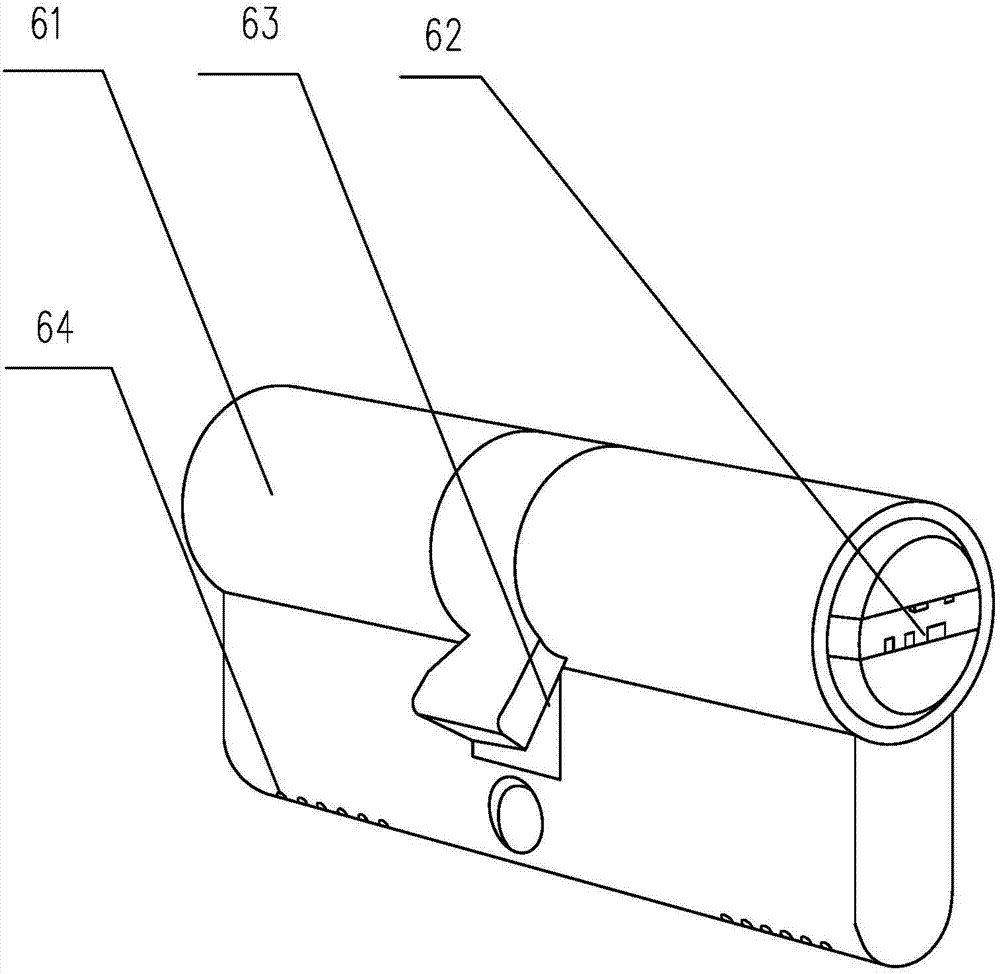
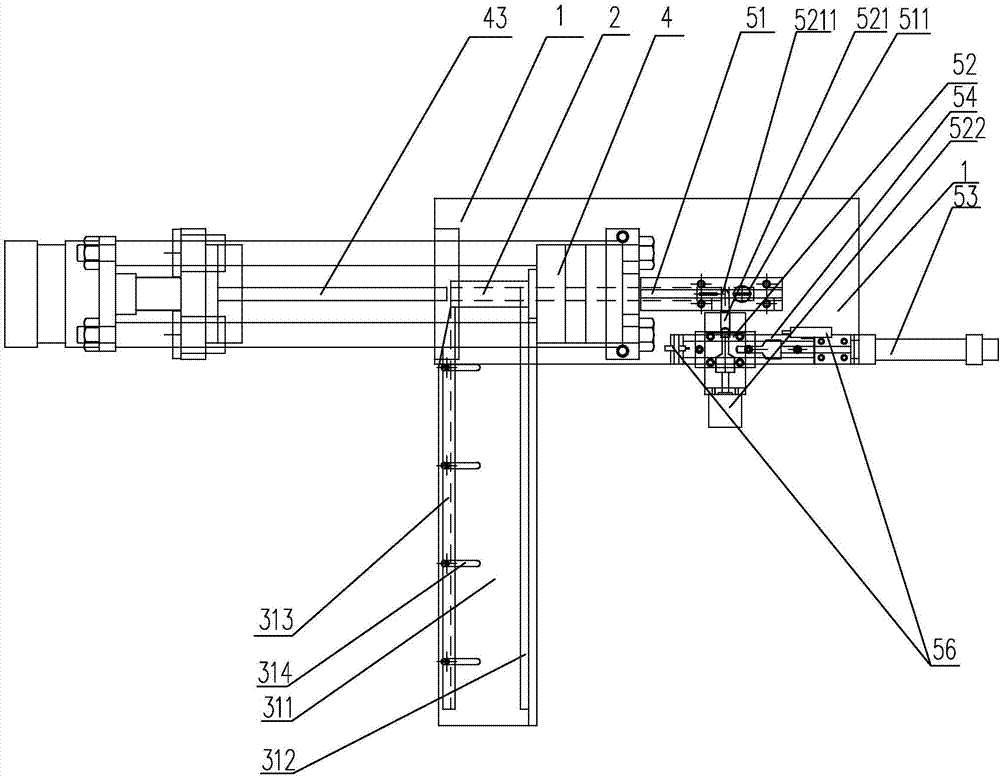
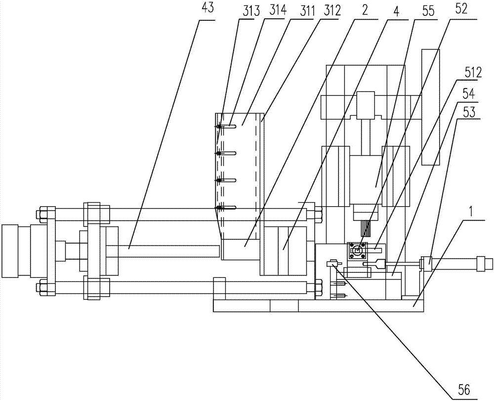
[0028] Depend on Figure 1 to Figure 6It can be seen that the present invention discloses a lock cylinder shell processing device, including a bracket 1, a feeding mechanism, a cutting mechanism 4 and a punching mechanism for punching the lock cylinder shell after the cutting is completed. The mechanism includes a punching chamber 51 and a punching machine 55. The feeding mechanism includes a housing chamber 2 and a feeding track for feeding materials into the housing chamber 2. The feeding track includes a bearing slide 31, and the bearing The slideway 31 is provided with a baffle plate 32 to prevent the lock core shell from turning over. The bearing slideway 31 includes a bearing bottom surface 311, a first side wall 313 and a second side wall 312. The bearing bottom surface 311 is provided with Adjustment groove 314, the second side wall 312 is fixed on the bearing bottom surface 311, the first side wall 313 is arranged on the adjustment groove 314 slidably along the adjust...


PUM


Abstract

The invention discloses a lock cylinder shell machining device. The lock cylinder shell machining device comprises a support, a feeding mechanism, a cutting mechanism and a hole punching mechanism used for performing hole punching on a lock cylinder shell where cutting is completed; the hole punching mechanism comprises a hole punching cavity and a hole punching machine; the feeding mechanism comprises a containing cavity and a feeding track used for feeding materials into the containing cavity; the cutting mechanism comprises a positioning cavity, a cutting cavity and an ejecting rod, and the ejecting rod is used for pushing and ejecting the lock cylinder shell to sequentially penetrate the positioning cavity and the cutting cavity from the containing cavity and then enter the hole punching cavity; a cutter used for cutting the peripheral face of the lock cylinder shell is arranged in the cutting cavity; the hole punching cavity is provided with a machining window used for hole punching operation; and the hole punching machine is arranged above the machining window. The lock cylinder shell machining device is simple and reasonable in structure, automatic operation can be achieved, the surface of the lock cylinder shell is cut and is subjected to hole punching, the production efficiency is improved, and the labor cost is reduced.

Description

technical field [0001] The invention relates to the technical field of hardware processing equipment, in particular to a treatment and processing equipment for surface treatment of a lock cylinder housing. Background technique [0002] The lock cylinder is the main part that controls the opening of the lock. It is the heart of the lock. figure 1 As shown, the lock cylinder usually includes a lock cylinder shell 61, a lock cylinder 62 and several marble assemblies arranged in them. The lock cylinder 62 is arranged in the lock cylinder shell 61, and the front end or the rear end of the lock cylinder shell is provided with pins for accommodating marbles. The opening 64 of the lock cylinder shell 61 is also provided with a through groove 63 for assembling or realizing cooperation with an external lock, so as to achieve the functions of unlocking and locking. In the processing of the lock cylinder shell, after the shell shape is produced by the mold, However, the surface of the ...

Claims


Application Information

Patent Timeline
Patent Type & Authority Applications(China)
IPC IPC(8): B23P23/04
CPCB23P23/04
Inventor 金勇
Owner 金勇
Why Eureka
Try Eureka