Aerostat launching system

A launch system and aerostat technology, applied in the aviation field, can solve problems such as high site requirements, and achieve the effects of easy control, simple structure, and reduced control process

Inactive Publication Date: 2017-11-07
DONGGUAN FRONTIER TECH INST
View PDF7 Cites 6 Cited by
  • Summary
  • Abstract
  • Description
  • Claims
  • Application Information

AI Technical Summary

Problems solved by technology

However, this type of dynamic launch method has high requirements for the site because the launch vehicle is requ

Method used


Image

  • Aerostat launching system
  • Aerostat launching system

Examples


Embodiment Construction

[0020] It should be noted that, in the case of no conflict, the embodiments in the present application and the features in the embodiments can be combined with each other. The present invention will be described in detail below with reference to the accompanying drawings and examples.

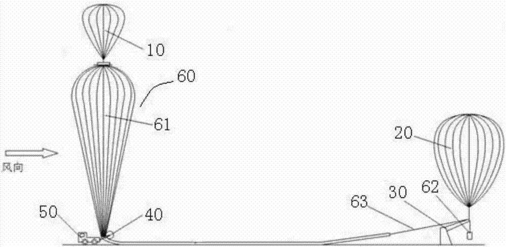
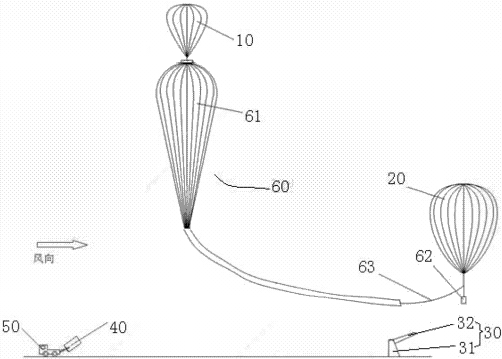
[0021] Such as figure 1 As shown, in the process of launching the aerostat 60, since the gas inside the balloon 61 of the aerostat 60 will expand greatly during the ascent process, only a part of the balloon 61 is inflated on the ground. Since some hard structures are usually installed on the balloon 61, in order to assist the erection process of the balloon 61, the present invention provides an aerostat launching system.

[0022] Such as figure 1 Shown is a schematic structural diagram of the aerostat launching system before the aerostat is launched, and the upwind side includes: the balloon 61 of the aerostat 60 carried by the mobile device 50, the first auxiliary balloon 10 and the aerosta...


PUM


Abstract

The invention provides an aerostat launching system. The aerostat launching system comprises a nurse balloon and a support, wherein the nurse balloon is connected with a to-be-launched aerostat to overhang the aerostat, and the support is used for hanging a pod of the aerostat. According to the aerostat launching system, righting of the aerostat is facilitated to enable the aerostat to be upright, when gas in the balloon of the aerostat is inflated to a certain amount, the balloon can rise through buoyancy force, accordingly, the pod is hung to be launched into the air, and the aerostat launching system is simple and convenient, and convenient to control.

Description

technical field [0001] The invention relates to the field of aviation technology, in particular to an aerostat launching system. Background technique [0002] At present, for the launch of large and heavy-duty balloons, the mainstream method adopted is the dynamic launch method. In this type of launch system, there is usually a movable dynamic launch vehicle, which constrains the pod below the balloon. and release at the right time. Generally speaking, the pods mounted on large balloons are usually larger, and the equipment in them is more sophisticated, so it needs to be suspended, and a dynamic launch vehicle with a boom can achieve this purpose. On the other hand , the dynamic launch vehicle moves with the balloon to realize the smooth release of the pod. For the sphere, a set of roller device is mainly used at present to constrain and release the sphere. In the superpressure balloon launch system of the United States, an auxiliary balloon is also added to the top of t...

Claims


Application Information

Patent Timeline
IPC IPC(8): B64B1/40
CPCB64B1/40
Inventor 不公告发明人
Owner DONGGUAN FRONTIER TECH INST
Why Eureka
Try Eureka