Multi-head discharging device of wet spraying machine

A discharge device and wet spraying machine technology, applied in the direction of shaft equipment, shaft lining, tunnel lining, etc., can solve the problems of unable to adjust the size of the discharge flow, and the discharge of wet sprayed concrete can not be effectively controlled, so as to improve the comfort of use degree of effect

Pending Publication Date: 2017-11-07
河南省耿力工程设备有限公司
View PDF10 Cites 0 Cited by
  • Summary
  • Abstract
  • Description
  • Claims
  • Application Information

AI Technical Summary

Problems solved by technology

[0003] The existing concrete spraying machine has the following defects: the original discharge pipeline cannot adjust the discharg

Method used


Image

  • Multi-head discharging device of wet spraying machine
  • Multi-head discharging device of wet spraying machine
  • Multi-head discharging device of wet spraying machine

Examples


Embodiment 1

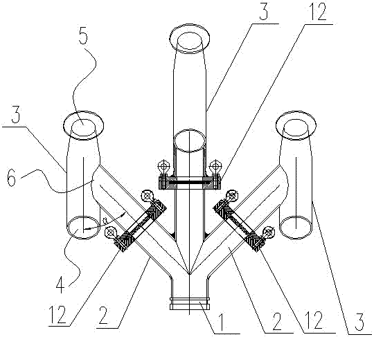
[0022] Such as Figure 1 to Figure 5 As shown, a multi-head discharge device of a wet spraying machine of the present invention includes a main pipe 1 communicated with a concrete delivery pipeline, and at least three branch pipes 2 connected thereto are fixed on the main pipe 1. Described branch pipe 2 is set as three. The discharge end of each branch pipe 2 is provided with an air material mixer 3, and the angle α between the central axis of the air material mixer 3 and the central axis of the corresponding branch pipe 2 is an acute angle, preferably 45°. The air material mixer 3 includes an air inlet 4 and a material outlet 5 which are arranged at both ends of the air material mixer 3 in the axial direction, and the air material mixer 3 is located at a position between the air inlet 4 and the material outlet 5 A feed inlet 6 is provided, and the air feed mixer 3 is connected to the discharge end of the corresponding branch pipe 2 at the feed inlet 6 .

[0023] Since the a...

Embodiment 2

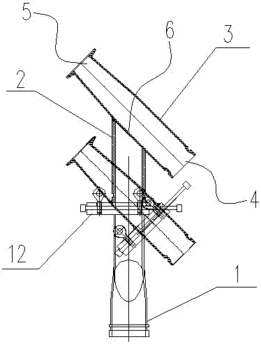
[0028] The difference between this embodiment and embodiment one is that the arrangement forms of the three branch pipes 2 and the air material mixer 3 are different, such as Image 6 As shown, the branch pipe 2 is provided with three, wherein the air material mixers 3 arranged on the two branch pipes 2 are parallel to each other, and the outlets 5 of the air material mixers all point to obliquely downward; The discharge port 5 of the air material mixer 3 points obliquely upwards.

[0029] The arrangement of the three branch pipes 2 and the air material mixer 3 is not limited to the above embodiment, and the arrangement of the air material mixer can also be arranged in other schemes.

[0030] The present invention arranges at least three branch pipes 2 and air material mixer 3, and each branch pipe 2 is equipped with a flow regulating structure, which can freely and flexibly switch the discharge port and control the amount of concrete spraying according to the demand of workin...


PUM


Abstract

The invention discloses a multi-head discharging device of a wet spraying machine. The multi-head discharging device comprises a main pipe communicating with a concrete conveying pipeline, the main pipe is fixedly provided with at least three branch pipes communicating with the main pipe, an air-material mixer is arranged at the discharging end of each branch pipe, and the included angle alpha between the central axis of each air-material mixer and the central axis of the corresponding branch pipe. Each air-material mixer comprises an air inlet and a discharge outlet, wherein the air inlet and the discharge outlet are formed in the two ends of the air-material mixer in the axial direction correspondingly, a feed inlet is formed in the position, located between the air inlet and the discharge outlet, of the air-material mixer, and the feed inlet of the air-material mixer is connected with the discharging end of the corresponding branch pipe. Each branch pipe is provided with a flow adjusting structure. The air-material mixers can be freely and flexibly switched and the concrete spraying amount can be controlled according to the required amount of working hours and working conditions, and production diversification requirements of users are met.

Description

technical field [0001] The invention relates to the technical field of concrete wet spraying machines, in particular to a multi-head discharge device for wet spraying machines. Background technique [0002] Concrete wet spraying machine is mainly used in engineering construction. Its basic principle is to use hydraulic pressure to transport the ready-mixed concrete to the air mixer through the pipeline, and use the energy of compressed air to spray the concrete at high speed to the sprayed surface. After setting and hardening, the concrete support layer is formed. [0003] The existing concrete spraying machine has the following defects: the original discharge and spray pipeline cannot adjust the discharge flow rate, and the discharge of wet sprayed concrete cannot be effectively controlled according to the pouring position and demand. Contents of the invention [0004] In order to solve the problems in the prior art, the present invention provides a multi-head discharge ...

Claims


Application Information

Patent Timeline
IPC IPC(8): E02D15/02E21D11/10
CPCE21D11/105E02D15/02
Inventor 许会俭张中心蔡文俊
Owner 河南省耿力工程设备有限公司
Why Eureka
Try Eureka