Anti-floating method for thin-walled square box in flat slab floor

A beamless floor and square box technology, which is applied to floors, building components, buildings, etc., can solve the problems of overall floating, square boxes are easy to float and shift, and the anti-buoyancy force is not in the same vertical direction. Floating, good anti-floating effect, reducing the effect of cumbersome construction process

Inactive Publication Date: 2017-11-07
SHANGHAI BAOYE GRP CORP
View PDF4 Cites 2 Cited by
  • Summary
  • Abstract
  • Description
  • Claims
  • Application Information

AI Technical Summary

Problems solved by technology

In the case of concrete buoyancy, vibration and disturbance, and excessive slump of concrete mixture, the square box is easy to float and shift, and may even float up as a whole
In many similar projects, the anti-floating measures of thin-walled square boxes are to use iron wires to connect and fix the steel bars at the lower part of the floor through the bottom formwork and the wooden purlins below, and then pass two horizontal and vertical anti-floating bars on the upper part of the square box. The floating reinforcement and the bottom reinforcement are well connected. However, there is a problem with this construction method that the anti-buoyancy force may not be in the same vertical direction. Because a large buoyancy force will be generated during the concrete pouring process and the vibration process, Therefore, it is easy to cause partial or even overall floating of the square box.

Method used


Image

  • Anti-floating method for thin-walled square box in flat slab floor

Examples


Embodiment Construction

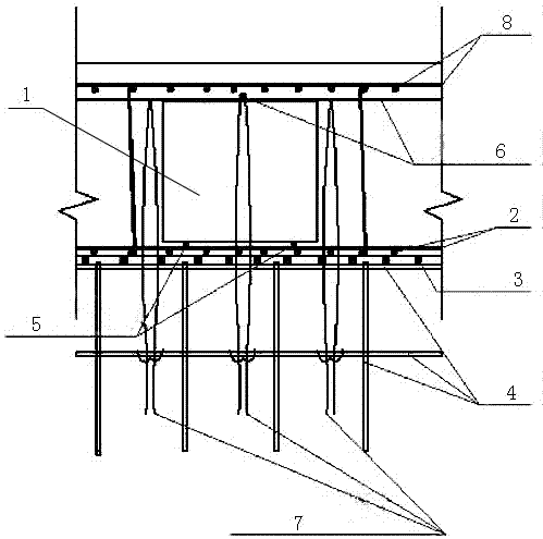
[0021] Such as figure 1 Shown: a thin-walled square box anti-floating method in a beamless floor, which includes the following steps:

[0022] Step 1: Construction preparation;

[0023] Check the appearance of the other box 1 one by one, and repair the damaged ones, and the height meets the deviation requirements, and the deviation is within ±10mm;

[0024] Step 2: Square box installation;

[0025] Install the bottom plate ribs 2 on the bottom plate formwork 3, and the lower part of the bottom plate formwork is provided with a supporting steel pipe frame 4, then transfer the square boxes to the bottom plate ribs with a hanging basket, and stack them in a scattered manner to avoid large concentrated loads, and play the grid well line, place pads 5 on the bottom plate reinforcement, and lift the square box on the pads, each square box corresponds to four pads, adjust the alignment to ensure that the square boxes and the square box and hidden beams, walls, The spacing between ...


PUM

PropertyMeasurementUnit
Heightaaaaaaaaaa
Diameteraaaaaaaaaa

Abstract

The invention relates to an anti-floating method for a thin-walled square box in a flat slab floor. The anti-floating method comprises the following steps that firstly, construction is prepared; secondly, the square box is mounted, specifically, a bottom plate rib is mounted on a bottom plate formwork, supporting steel pipe frames are arranged below the bottom plate formwork, then the square box is hoisted onto the bottom plate rib through a hoisting basket, cushion blocks are placed on the bottom plate rib, and the square box is lifted and put onto the cushion blocks; and thirdly, the thin-walled square box is subjected to anti-floating fixing, specifically, two steel bars are arranged on the square box, the two steel bars are arranged in a crossed mode to be in a cross shape, then the steel bars and the supporting steel pipe frames below the bottom plate formwork are fixed in a bound mode through steel wires, reinforcing bars longitudinally and transversely arranged are arranged on the upper portions of the two steel bars, and at the four edges of the square box, the two cross-shaped steel bars which press the box tops are fixed to the supporting steel pipe frames in a bound mode through the steel wires. The problem of upward-floating of the thin-walled square box in the concrete pouring and vibrating processes is effectively solved, the construction efficiency is improved, the construction progress is accelerated, and a quite good anti-floating effect is achieved, so that the construction progress is accelerated. Certain reference and popularization significance is achieved for a similar construction technology.

Description

technical field [0001] The invention relates to an anti-floating method, in particular to a method for anti-floating of a thin-walled square box in a beamless floor. Background technique [0002] In previous projects, square boxes were installed in most areas of the entire podium to reduce dead weight and improve rigidity. After the steel bars and pre-embedded, reserved and pipes in the lower part of the floor are installed, effective anti-floating measures should be taken for the placed thin-walled square boxes. When the buoyancy of the concrete, the vibrating action and the slump of the concrete mixture are too large, the square box is easy to float and shift, and may even float up as a whole. In many similar projects, the anti-floating measures of thin-walled square boxes are to use iron wires to connect and fix the steel bars at the lower part of the floor through the bottom formwork and the wooden purlins below, and then pass two horizontal and vertical anti-floating b...

Claims


Application Information

Patent Timeline
IPC IPC(8): E04B5/36
CPCE04B5/36
Inventor 赵文志王孟高伟伟赵斌
Owner SHANGHAI BAOYE GRP CORP
Why Eureka
Try Eureka