Eureka AIR delivers breakthrough ideas for toughest innovation challenges, trusted by R&D personnel around the world.

Micro diaphragm pump upper end cover

A technology of micro-diaphragm pumps and end caps, applied to pumps, pump components, variable-capacity pump components, etc., can solve the problems of complex structure, troublesome assembly, and many parts, and achieve small volume, convenient assembly, and few parts Effect

Active Publication Date: 2020-07-03
宁波九缘菲力加泵业有限公司
View PDF9 Cites 0 Cited by
  • Summary
  • Abstract
  • Description
  • Claims
  • Application Information

AI Technical Summary

Problems solved by technology

[0003] At present, RO pumps have relatively large vibrations and relatively large noises during use. The prior art uses a shock absorbing and noise reduction device on the outside of the RO pump head cover. For example, the publication number is CN 104776014 A, and the name is water purifier and its Disclosure of diaphragm pump assembly "a diaphragm pump assembly of a water purifier, characterized in that it includes: a pump body, the pump body has a water outlet; a damping device, the damping device includes: a first housing, the first A housing has a water inlet, the water inlet is connected to the water outlet; a second housing, the second housing has a water outlet, the second housing is connected to the first housing and connected to the water outlet The first housing defines a buffer space, wherein the buffer space is respectively connected to the water inlet and the water outlet; a damper, the damper is arranged in the buffer space and is elastically deformed by hydraulic pressure
", but this kind of mechanism has complex structure, more parts, higher cost, and more troublesome assembly

Method used


Image

  • Micro diaphragm pump upper end cover
  • Micro diaphragm pump upper end cover
  • Micro diaphragm pump upper end cover

Examples


Embodiment 1

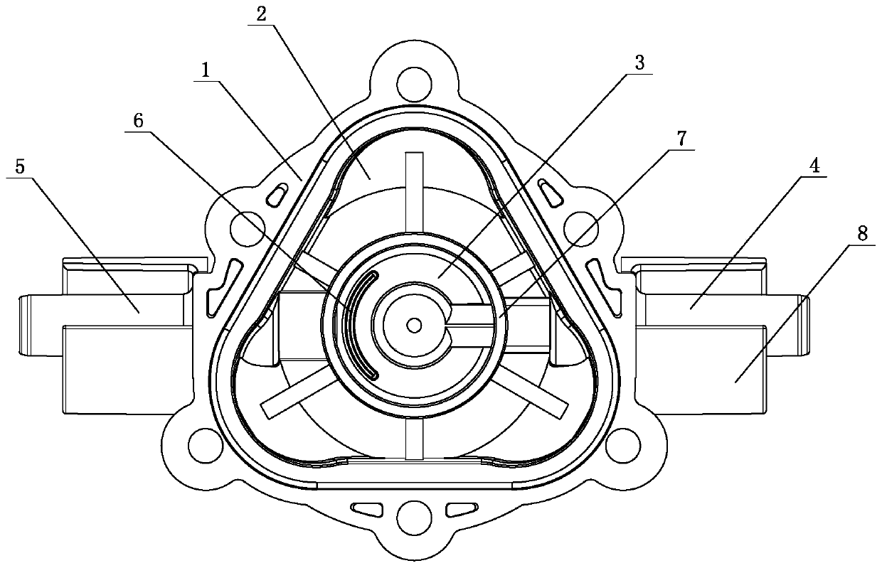
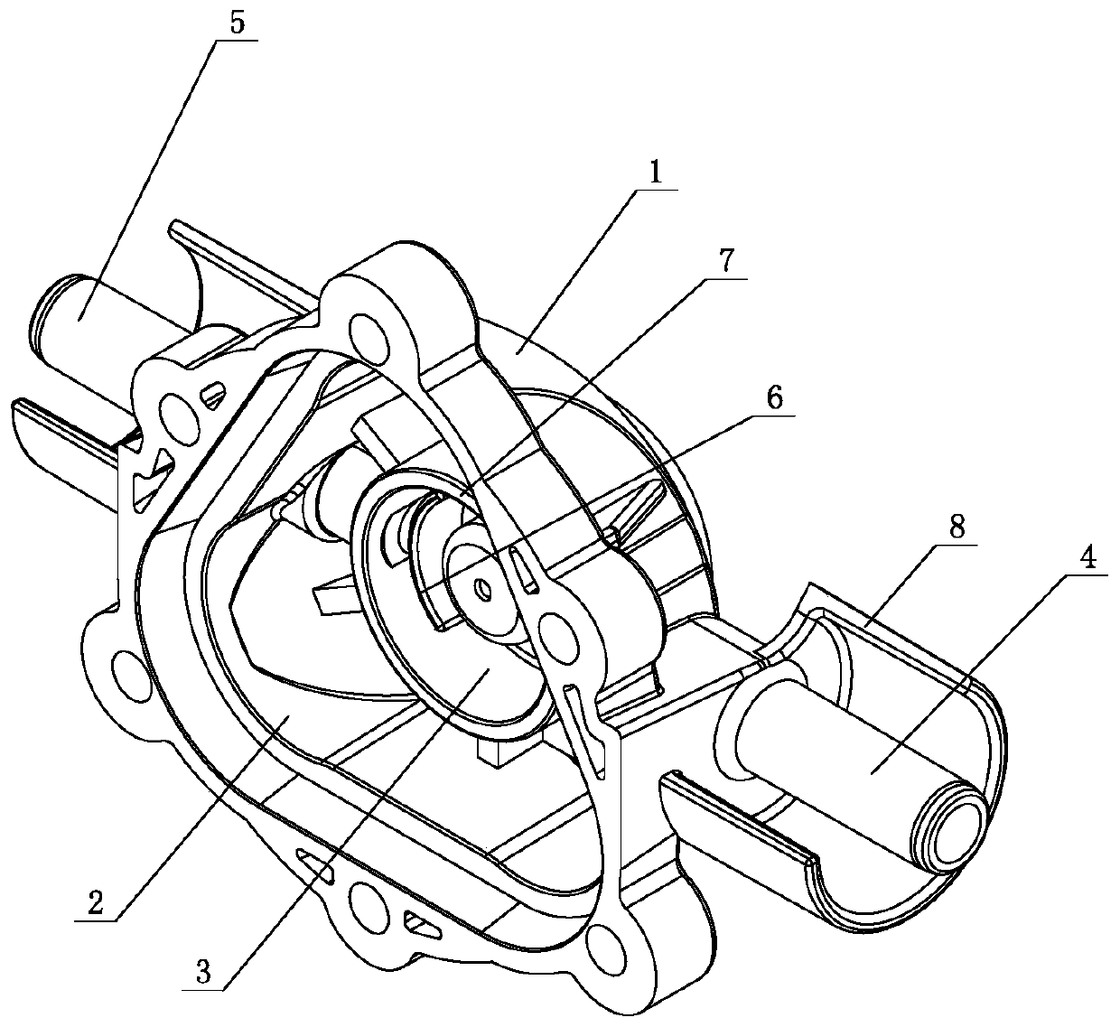
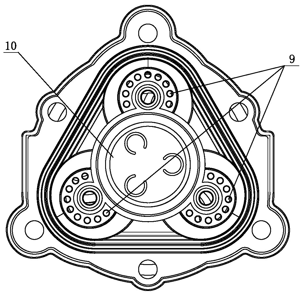
[0022] Such as figure 1 and figure 2 Shown, a kind of micro-diaphragm pump upper end cover, it comprises the cover body 1 that covers on the micro-diaphragm pump head, and the micro-diaphragm pump head that cover body 1 covers (seeing image 3 ) position, the head of the micro-diaphragm pump is provided with a water inlet 9 and a water outlet 10, and the water inlet 9 and the water outlet 10 are provided with a one-way valve plate, and the cover body 1 is provided with a water inlet chamber 2 and a water outlet chamber 3, and the two sides of the cover body 1 are respectively provided with a water inlet pipe 4 and a water outlet pipe 5, the water inlet pipe 4 communicates with the water inlet chamber 2, the water outlet pipe 5 communicates with the water outlet chamber 3, and the water outlet chamber 3 is provided with The water baffle 6 prevents the outlet water from the water outlet 10 of the head of the micro-diaphragm pump from directly entering the outlet pipe 5 . The ...

Embodiment 2

[0030] A kind of micro-diaphragm pump upper end cover, it comprises the cover body 1 that covers on the micro-diaphragm pump head, and the micro-diaphragm pump head that cover body 1 covers (see image 3 ) position, the head of the micro-diaphragm pump is provided with a water inlet 9 and a water outlet 10, and the water inlet 9 and the water outlet 10 are provided with a one-way valve plate, and the cover body 1 is provided with a water inlet chamber 2 and a water outlet chamber 3, and the two sides of the cover body 1 are respectively provided with a water inlet pipe 4 and a water outlet pipe 5, the water inlet pipe 4 communicates with the water inlet chamber 2, the water outlet pipe 5 communicates with the water outlet chamber 3, and the water outlet chamber 3 is provided with The water baffle 6 prevents the outlet water from the water outlet 10 of the head of the micro-diaphragm pump from directly entering the outlet pipe 5 . The water inlet 9 of the head of the micro-diap...

Embodiment 3

[0033] A kind of micro-diaphragm pump upper end cover, it comprises the cover body 1 that covers on the micro-diaphragm pump head, and the micro-diaphragm pump head that cover body 1 covers (see image 3) position, the head of the micro-diaphragm pump is provided with a water inlet 9 and a water outlet 10, and the water inlet 9 and the water outlet 10 are provided with a one-way valve plate, and the cover body 1 is provided with a water inlet chamber 2 and a water outlet chamber 3, and the two sides of the cover body 1 are respectively provided with a water inlet pipe 4 and a water outlet pipe 5, the water inlet pipe 4 communicates with the water inlet chamber 2, the water outlet pipe 5 communicates with the water outlet chamber 3, and the water outlet chamber 3 is provided with The water baffle 6 prevents the outlet water from the water outlet 10 of the head of the micro-diaphragm pump from directly entering the outlet pipe 5 . The water inlet 9 of the head of the micro-diaph...


PUM


Abstract

The invention relates to a miniature diaphragm pump upper end cover. The miniature diaphragm pump upper end cover comprises a cover body (1) covering a miniature diaphragm pump head, the cover body (1) is internally provided with a water inlet cavity (2) and a water outlet cavity (3), a water inlet pipe (4) and a water outlet pipe (5) are further arranged on the two sides of the cover body (1), the water inlet pipe (4) is communicated with the water inlet cavity (2), and the water outlet pipe (5) is communicated with the water outlet cavity (3). The miniature diaphragm pump upper end cover is characterized in that a water stopping plate (6) is arranged in the water outlet cavity (3) so that outlet water of the water outlet end of the miniature diaphragm pump head cannot directly enter the water outlet pipe (5). Compared with the prior art, the miniature diaphragm pump upper end cover has the beneficial effects that the structure is simple, the size is small, the weight is small, the number of parts is small, assembling is convenient, vibration attenuation and noise elimination can be achieved, the evacuation and self-suction capacity is strengthened, and the machining and installing cost can be greatly reduced.

Description

Technical field: [0001] The invention belongs to the field of water pump equipment, in particular to an upper end cover of a miniature diaphragm pump. Background technique: [0002] Micro diaphragm pump (RO pump), also known as RO booster pump, RO self-priming pump, reverse osmosis booster pump, reverse osmosis self-priming pump, etc., is a kind of DC diaphragm booster pump. The English name of the RO pump is Reverse Osmosis Diaphragm Pump, and the complete Chinese meaning is reverse osmosis (reverse osmosis) diaphragm booster pump. At present, it is one of the core accessories of the water purification industry and household water purifiers. [0003] At present, RO pumps have relatively large vibrations and relatively large noises during use. The prior art uses a shock absorbing and noise reduction device on the outside of the RO pump head cover. For example, the publication number is CN 104776014 A, and the name is water purifier and its Disclosure of diaphragm pump asse...

Claims


Application Information

Patent Timeline
Patent Type & Authority Patents(China)
IPC IPC(8): F04B43/02F04B53/16F04B53/00
CPCF04B43/02F04B53/001F04B53/16
Inventor 葛家伟陈财兵袁杰生
Owner 宁波九缘菲力加泵业有限公司
Why Eureka
Eureka Blog
Learn More