
Leakproof faucet

A water faucet and anti-leakage technology, which is applied in the field of faucets, can solve the problems of water resource waste, water leakage, and hydraulic cylinder pressure can not be adjusted, and achieve the effect of meeting the needs of use, controlling the water output, and good water output

Inactive Publication Date: 2017-11-07
广州酷刻科技有限公司
View PDF1 Cites 8 Cited by
  • Summary
  • Abstract
  • Description
  • Claims
  • Application Information

AI Technical Summary

Problems solved by technology

[0002] Faucet is the popular name of water valve, which is used to control the size of the water flow and has the effect of saving water. The replacement speed of faucets is very fast, from old-fashioned cast iron technology to electroplating knob type, and to stainless steel single-temperature single-control faucet , stainless steel dual-temperature dual-control faucet, kitchen semi-automatic faucet, now, more and more consumers choose faucets, they will comprehensively consider materials, functions, shapes and other aspects. Today's society has been in a state of water shortage, so Saving water is very important. However, water leakage often occurs in current faucets, resulting in a waste of water resources. In the prior art, such as the utility model patent with application number 201620569170.6, it includes the main body of the faucet, and the bottom of the main body of the faucet A water outlet pipe is connected, and the end of the water outlet pipe away from the main body of the faucet is provided with a water outlet. A hydraulic cylinder is fixedly connected to the inner wall of the end of the main body away from the water inlet. A piston is arranged inside the hydraulic cylinder, and a hydraulic rod is fixedly connected to the right side of the piston. Although this utility model can install the faucet and the water pipe more tightly, However, the pressure of the hydraulic cylinder cannot be adjusted, and the water output is not easy to control, which cannot meet the needs of users.

Method used


Image

  • Leakproof faucet
  • Leakproof faucet
  • Leakproof faucet

Examples


Embodiment Construction

[0015] The following will clearly and completely describe the technical solutions in the embodiments of the present invention with reference to the accompanying drawings in the embodiments of the present invention. Obviously, the described embodiments are only some, not all, embodiments of the present invention. Based on the embodiments of the present invention, all other embodiments obtained by persons of ordinary skill in the art without making creative efforts belong to the protection scope of the present invention.

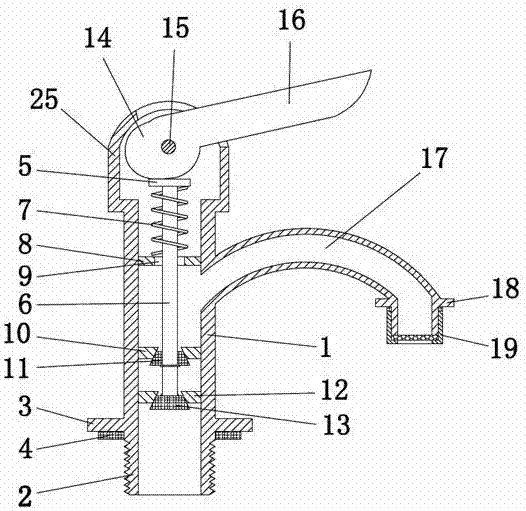
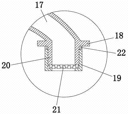
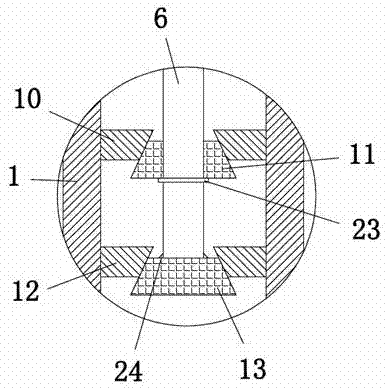
[0016] see Figure 1-3 , the present invention provides a technical solution: a leak-proof faucet, including a faucet body 1, the bottom of the faucet body 1 is provided with a water inlet 2, the water inlet 2 is connected to a water supply pipeline, and the top of the outer wall of the water inlet 2 is installed with a first Clamp 3, the bottom end of the first clamp 3 is equipped with a rubber pad 4, the rubber pad 4 makes the connection between the water in...


PUM


Abstract

The invention discloses a leak-proof faucet, which comprises a faucet body, a water inlet is provided at the bottom end of the faucet body, a spring seat is provided at the inner top end of the faucet body, and a compression spring is installed at the top end of the spring seat, so that A sliding rod is sleeved inside the compression spring, a first water plug is installed at the bottom end of the outer wall of the sliding rod, and a second water plug is installed at the bottom end of the sliding rod. In this leak-proof water faucet, through the cooperation of the first water plug, the second water plug and the slide bar, the right end of the handle is pressed down, and the handle drives the pressing block to rotate clockwise. The function makes the baffle move upwards, and the baffle drives the sliding rod to move upwards, the sliding rod drives the first water to block the first conical seat, and the second water to block the second conical seat, water will not flow from the first conical seat and The hole in the middle of the second conical seat flows through, which is better for preventing water leakage, and the water output is easy to control, which can meet the needs of users.

Description

technical field [0001] The invention relates to the technical field of faucets, in particular to a leak-proof faucet. Background technique [0002] Faucet is the popular name of water valve, which is used to control the size of the water flow and has the effect of saving water. The replacement speed of faucets is very fast, from old-fashioned cast iron technology to electroplating knob type, and to stainless steel single-temperature single-control faucet , stainless steel dual-temperature dual-control faucet, kitchen semi-automatic faucet, now, more and more consumers choose faucets, they will comprehensively consider materials, functions, shapes and other aspects. Today's society has been in a state of water shortage, so Saving water is very important. However, water leakage often occurs in current faucets, resulting in a waste of water resources. In the prior art, such as the utility model patent with application number 201620569170.6, it includes the main body of the fauc...

Claims


Application Information

Patent Timeline
Patent Type & Authority Applications(China)
IPC IPC(8): F16K1/00F16K1/44F16K31/524
CPCF16K1/00F16K1/44F16K31/5245
Inventor 张帆
Owner 广州酷刻科技有限公司
Learn More