Rotational scanning equipment

A technology of rotating scanning and equipment, which is applied in the field of optical detection, can solve problems such as unproposed solutions, synchronization accuracy depends on the installation angle of the laser transceiver, troublesome debugging, etc., to reduce equipment complexity, improve system stability, and reduce production costs Effect

Active Publication Date: 2017-11-07
CHINA HEFEI TAIHE OPTOELECTRONICS TECH
View PDF10 Cites 0 Cited by
  • Summary
  • Abstract
  • Description
  • Claims
  • Application Information

AI Technical Summary

Problems solved by technology

However, this implementation method is costly, troublesome to debug, and the synchronization accuracy must depend on the installation angle of the laser transceiver
[0004] Aiming at the above problems in related technologies, no effective solution has been proposed yet

Method used


Image

  • Rotational scanning equipment
  • Rotational scanning equipment
  • Rotational scanning equipment

Examples


Embodiment Construction

[0022] The following will clearly and completely describe the technical solutions in the embodiments of the present invention with reference to the accompanying drawings in the embodiments of the present invention. Obviously, the described embodiments are only some, not all, embodiments of the present invention. All other embodiments obtained by persons of ordinary skill in the art based on the embodiments of the present invention belong to the protection scope of the present invention.

[0023] According to an embodiment of the present invention, a rotary scanning device is provided.

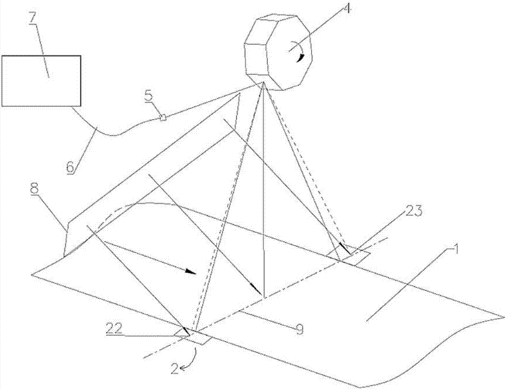
[0024] refer to figure 1 As shown, the rotary scanning device according to the embodiment of the present invention includes: a light source 8, a synchronous signal generator 2, a rotating prism 4, and a data acquisition and processing module 7; wherein the synchronous signal generator 2 is a passive synchronous signal generator 2 and wherein, the light signal sent by the light source 8 is irra...


PUM


Abstract

The invention discloses rotational scanning equipment, which comprises a light source, a synchronizing signal generator, a rotary prism and a data acquiring and processing module. The synchronizing signal generator is a passive synchronizing signal generator; a light signal emitted by the light source is irradiated on a conveyer belt of a material and the synchronizing signal generator; the light signal reflected through the material and the synchronizing signal generator is reflected to the rotary prism; the light signal re-reflected by the rotary prism is transmitted to the data acquiring and processing module; the data acquiring and processing module processes the re-reflected light signal and acquires a synchronizing signal. According to the rotational scanning equipment provided by the invention, the synchronizing signal is extracted from the light signal reflected from the synchronizing signal generator and the material through the data acquiring and processing module, so that an optical path design is optimized, the equipment complexity is reduced, the system stability is improved, and the production cost is reduced.

Description

technical field [0001] The invention relates to the technical field of optical detection, in particular to a rotating scanning device. Background technique [0002] In the rotary scanning equipment, the function of the synchronous signal is very critical. A high-precision and effective synchronous signal can ensure the repeated and stable operation of the system. Once the synchronous signal is lost, the system operation will be disordered, just like a magnet placed on a mechanical watch. As above, accurate timing is not possible. [0003] In the prior art, a general rotary scanning device usually uses a laser light source and a laser receiving head as a synchronization signal generator and receiver, and assists hardware circuits to realize the synchronization function. However, this implementation method is costly and troublesome to debug, and the synchronization accuracy must depend on the installation angle of the laser transceiver. [0004] For the above-mentioned probl...

Claims


Application Information

Patent Timeline
Patent Type & Authority Applications(China)
IPC IPC(8): G01N21/01
CPCG01N21/01
Inventor 颜天信章广飞杨贤良
Owner CHINA HEFEI TAIHE OPTOELECTRONICS TECH
Why Eureka
Try Eureka