
Backlight module, control method thereof and display device

A backlight module and display device technology, applied to static indicators, instruments, etc., can solve the problems of large power consumption, unfavorable energy saving, and large power consumption

Inactive Publication Date: 2017-11-07
BOE TECH GRP CO LTD +1
View PDF9 Cites 31 Cited by
  • Summary
  • Abstract
  • Description
  • Claims
  • Application Information

AI Technical Summary

Problems solved by technology

[0003] In the prior art, the driving mode of the backlight module is a driving mode in which the entire backlight is turned on and off at the same time, and in the process of image display, the backlight is always on, and the power consumption in this mode is relatively large , which is not conducive to energy saving, especially for large-size LCD image display systems. In order to meet the display requirements, a large-size backlight module needs to be equipped, resulting in greater power consumption

Method used


Image

  • Backlight module, control method thereof and display device
  • Backlight module, control method thereof and display device
  • Backlight module, control method thereof and display device

Examples


Embodiment Construction

[0051] In order to make the purpose, technical solutions and advantages of the present invention clearer, the present invention will be further described in detail below in conjunction with the accompanying drawings. Obviously, the described embodiments are only some of the embodiments of the present invention, rather than all of them. Based on the embodiments of the present invention, all other embodiments obtained by persons of ordinary skill in the art without making creative efforts belong to the protection scope of the present invention.

[0052] The specific implementation manners of the backlight module, its control method and display device provided by the embodiments of the present invention will be described in detail below with reference to the accompanying drawings.

[0053] Wherein, the thickness and shape of each film layer in the drawings do not reflect the real scale, and the purpose is only to illustrate the content of the present invention.

[0054] The backl...


PUM


Abstract

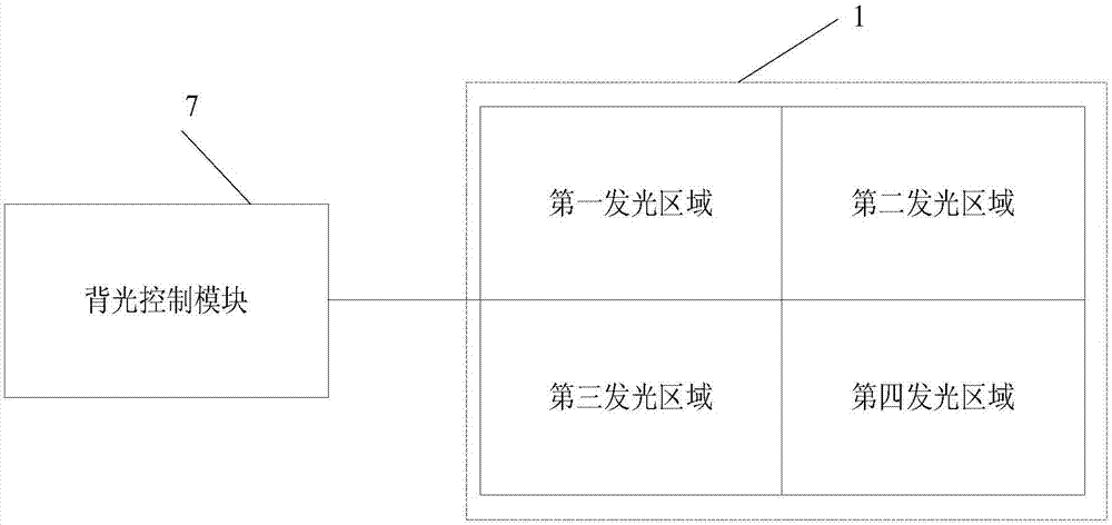
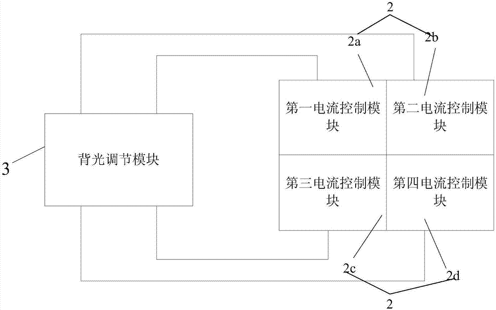
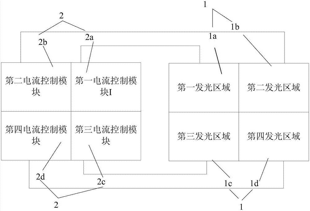
The invention discloses a backlight module, a control method thereof and a display device. The backlight module comprises a backlight source composed of a plurality of light emitting devices arranged in a matrix mode. The backlight source comprises a plurality of light emitting regions. A display panel comprises a plurality of display regions. The display regions correspond to the light emitting regions one to one; the backlight module further comprises a backlight control module; when the backlight control module is scanned at the display regions of the display panel, light emitting devices inside the light emitting regions corresponding to the display regions are controlled to emit light. By dividing the backlight source, time-sharing driving is performed, in other words, when the regions, corresponding to the light emitting regions, of the display panel are scanned, the light emitting devices inside the light emitting regions are controlled to emit light, and the light emitting regions corresponding to the regions, not scanned, in the display panel do not emit light, so that the light emitting time of each light emitting device in the backlight source is greatly shortened, a large amount of electric energy is saved, and due to time-sharing driving of the light emitting regions, crosstalk between the left and right eyes can be reduced during 3D scanning.

Description

technical field [0001] The invention relates to the field of display technology, in particular to a backlight module, its control method and a display device. Background technique [0002] Liquid crystal display panel (LCD, Liquid Crystal Display) has many advantages such as thin body, power saving, and no radiation, and has been widely used, such as: LCD TV, mobile phone, personal digital assistant (PDA), digital camera, computer screen or laptop screen etc. The structure of the liquid crystal display panel is mainly composed of a thin film transistor array substrate (ThinFilm Transistor Array Substrate, TFT Array Substrate), an opposite substrate, a common electrode layer located on the opposite substrate side, and a liquid crystal layer (Liquid Crystal) disposed between the two substrates. Layer), wherein the array substrate is provided with pixel electrodes, data lines and gate lines, and its working principle is to control the rotation of liquid crystal molecules in th...

Claims


Application Information

Patent Timeline
IPC IPC(8): G09G3/34
CPCG09G3/3406G09G2310/024G09G3/3426G09G2310/0283G09G3/003G09G2310/08G09G2320/0626
Inventor 陆政华何宗泽孟智明李硕杨建光冯志鹏张亮陈宇轩龙凤
Owner BOE TECH GRP CO LTD
Learn More