
A vacuum interrupter contact for switching capacitor banks and its control method

A technology of vacuum interrupter and switching capacitors, which is applied to circuits, electric switches, electrical components, etc., can solve the problems of reducing the insulation withstand voltage assessment of vacuum interrupter, reducing the probability of re-breakdown of vacuum interrupter, and operating control Difficulty and other problems, to achieve the effect of reducing insulation withstand voltage assessment, reducing fusion welding damage, and less difficulty

Active Publication Date: 2021-04-30
CHINA ELECTRIC POWER RES INST +3
View PDF6 Cites 0 Cited by
  • Summary
  • Abstract
  • Description
  • Claims
  • Application Information

AI Technical Summary

Problems solved by technology

[0005] In order to overcome the disadvantages of high re-breakdown probability, high cost, and difficult operation and control of vacuum interrupters in the prior art, a special physical phenomenon of switching capacitive loads in vacuum interrupters is proposed. The contact structure of the vacuum interrupter of the capacitor bank can effectively limit the amplitude of the high-frequency inrush current during the closing process, reduce its welding damage to the contact surface, and also effectively limit the recovery voltage during the opening process. Amplitude, reduce the insulation withstand voltage assessment of the vacuum interrupter, thereby reducing the probability of re-breakdown of the vacuum interrupter

Method used


Image

  • A vacuum interrupter contact for switching capacitor banks and its control method
  • A vacuum interrupter contact for switching capacitor banks and its control method
  • A vacuum interrupter contact for switching capacitor banks and its control method

Examples


Embodiment Construction

[0026] The present invention will be further described in detail below in conjunction with the accompanying drawings.

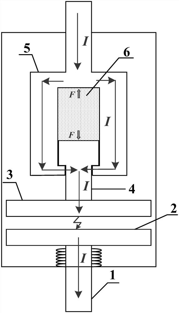
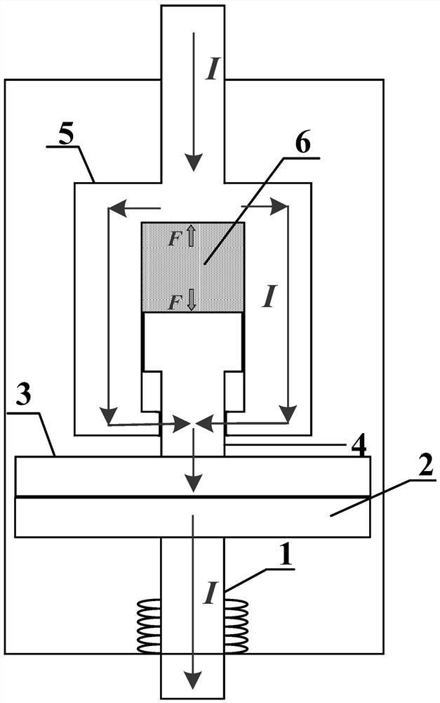
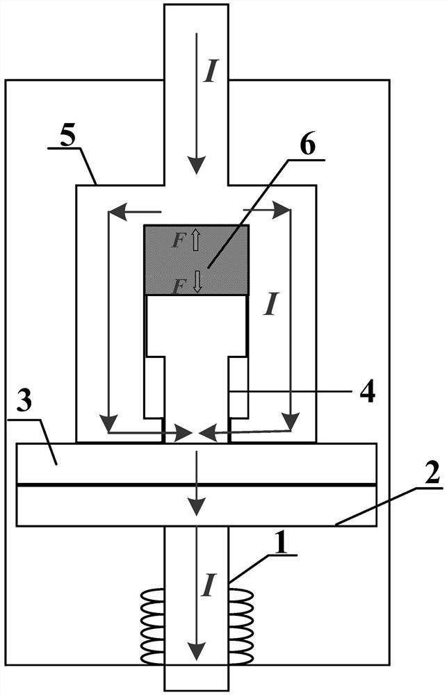
[0027] The present invention provides a vacuum interrupter contact suitable for switching capacitor banks, including a shield cover, a moving conductive rod 1, a static conductive rod 5, a first contact 3, a second contact 2 and a limiting resistor 4;

[0028] The moving conductive rod, the static conductive rod, the first contact, the second contact and the limiting resistor are arranged inside the shield;

[0029] One end of the limiting resistor 4 is fixedly connected to the first contact 3, and the other end is slidably connected to the static conductive rod;

[0030] One end of the moving conductive rod 1 is fixedly connected with the second contact 2 .

[0031] The static conduction rod 5 includes a conduction rod and a cavity with an opening in the middle of one end connected to the conduction rod and the other end in the middle.

[0032] One end of ...


PUM


Abstract

The invention provides a vacuum interrupter contact for switching capacitor banks and a control method thereof, the contact includes a shield cover, a moving conductive rod, a static conductive rod, a first contact, a second contact and Limiting resistance; one end of the limiting resistance is fixedly connected to the first contact, and the other end is slidingly connected to the static conductive rod; one end of the moving conductive rod is fixedly connected to the second contact; the moving conductive rod, the static conductive rod, the second The first contact, the second contact and the limiting resistor are arranged inside the shielding case. The technical solution provided by the invention effectively limits the amplitude of the high-frequency inrush current generated when the capacitor bank is closed by installing a limiting resistor, reduces its welding damage to the contact surface, and limits the recovery voltage when the capacitor bank is opened, reducing the For the insulation withstand voltage assessment of the vacuum interrupter, reduce the probability of heavy breakdown.

Description

technical field [0001] The invention relates to a vacuum interrupter contact, in particular to a vacuum interrupter contact for switching capacitor banks and a control method thereof. Background technique [0002] During the operation of the medium-voltage reactive power compensation system, due to frequent fluctuations in the grid load, in order to adjust the system power factor, reduce harmonics, stabilize voltage and reduce losses, capacitive loads will be frequently switched on and off. According to the operation experience of my country's power grid, 1.2kvar to 1.4kvar of reactive power is required for every 1kW of active power to maintain the normal working voltage of the power grid. According to foreign research and investigation, the application of vacuum circuit breakers in capacitive current operations can reach 300-700 times a year, that is, there are 1-2 opening and closing operations per day. For such frequent operating tasks, compared with other gas switches, ...

Claims


Application Information

Patent Timeline
Patent Type & Authority Patents(China)
IPC IPC(8): H01H33/664H01H33/666
CPCH01H33/664H01H33/666
Inventor 范闻博盛万兴吴燕王哲关洪涛余永祥李昊旻耿英三
Owner CHINA ELECTRIC POWER RES INST
Features
  • Generate Ideas
  • Intellectual Property
  • Life Sciences
  • Materials
  • Tech Scout
  • Unparalleled Data Quality
  • Higher Quality Content
  • 60% Fewer Hallucinations
Learn More