Common mode current suppression circuit of motor drive system

A motor drive system and common-mode current technology, applied in electrical components, output power conversion devices, etc., can solve the problems of reduced common-mode current suppression effect and increased common-mode current, so as to achieve the reduction and increase of common-mode current Loop impedance, effect of achieving common mode current

Active Publication Date: 2017-11-07
UNIV OF ELECTRONICS SCI & TECH OF CHINA
View PDF5 Cites 2 Cited by
  • Summary
  • Abstract
  • Description
  • Claims
  • Application Information

AI Technical Summary

Problems solved by technology

[0003] At present, commonly used common-mode current suppression circuits such as figure 2 As shown, three capacitors are connected in parallel between the inverter output terminal and the motor input terminal to provide a high-frequency loop so that the common-mode current can flow away from the capacitor. However, due to the parasitic Capacitors, if parallel capacitors are used to suppress the common-mode current, multiple high-frequency current loops will appear, and at this time, the suppression effect of the common-mode current will be reduced; at the same time, the circuit is equivalent to the original common-mode current loop A small impedance loop is connected in parallel, which will actually increase the common mode current in the entire system, which may make the electromagnetic interference in the system more obvious

Method used


Image

  • Common mode current suppression circuit of motor drive system
  • Common mode current suppression circuit of motor drive system
  • Common mode current suppression circuit of motor drive system

Examples


Embodiment Construction

[0027] The present invention will be further described in detail below in conjunction with specific embodiments and accompanying drawings.

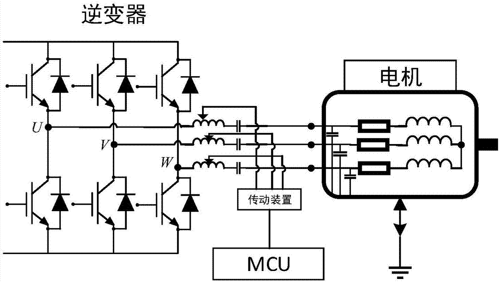
[0028] In this embodiment, a common-mode current suppression circuit for a motor drive system is provided, and its circuit structure is as follows figure 1 As shown, an LC filter circuit composed of an adjustable inductor L and a non-polar capacitor C is connected in series between the inverter output and the motor input. The value of the capacitor C is fixed at 100uF, and the inductance of the inductor L is controlled by the MCU. Transmission adjustment.

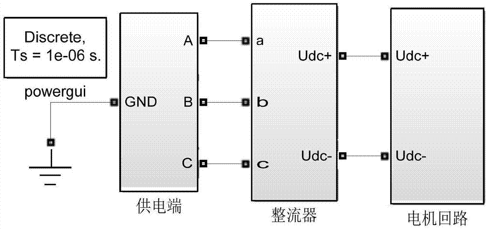
[0029] Simulation block diagram as image 3 As shown, the simulation block diagrams of the power supply circuit, rectifier circuit, inverter circuit and motor are shown in Figure 4 , Figure 5 , Figure 6 As shown; in the simulation, the carrier of the inverter control circuit is a 20kHz sawtooth wave, the modulation wave is a 50Hz sine signal, the inductance L of the common mode...


PUM


Abstract

The present invention belongs to the technical field of power electronics and provides a common mode current suppression circuit of a motor drive system for solving the interference of high frequency interference generated by a controllable rectifier and an inverter on a motor drive system and surrounding devices. The present invention includes three LC filter circuits, a transmission device and a micro control unit; the three LC filter circuits are respectively connected in series between the inverter output end and the motor input end, each LC filter circuit is formed by an adjustable inductor and a non-polar capacitor connected in series; the micro control unit controls the transmission device according to the frequency of the modulated wave signal output by the inverter; and the transmission device controls the inductance value of the adjustable inductor in each LC filter circuit separately by a sliding sheet, so that the driving current of the motor reaches the resonance in the LC filter circuit . The common mode current suppression circuit effectively suppresses the total conduction path of the common mode current to realize the common mode current suppression of the motor drive system, and ensures that the driving signal of the motor cannot be attenuated.

Description

technical field [0001] The invention belongs to the technical field of power electronics, and in particular relates to a common-mode current suppression circuit for a motor drive system. Background technique [0002] With the development of modern society, the requirements for the speed of the motor are getting higher and higher, and the switching frequency of the switching devices in the motor drive system is getting higher and higher. Due to the existence of high-frequency du / dt and parasitic capacitance, it will provide impedance for high-frequency signals Smaller circuits, these high-frequency current signals can cause serious electromagnetic interference (EMI) to the motor drive system. For example, the high-frequency common-mode current forms high-frequency electromagnetic radiation, which causes a certain induced current in the closed loop of surrounding equipment and the system itself. Therefore, in order to ensure that the system can work normally when the motor is...

Claims


Application Information

Patent Timeline
Patent Type & Authority Applications(China)
IPC IPC(8): H02M1/12
CPCH02M1/126H02M1/123
Inventor 毕闯董亮金顶鑫
Owner UNIV OF ELECTRONICS SCI & TECH OF CHINA
Why Eureka
Try Eureka