
Installing cabinet for communication system information switch

A technology for communication system and cabinet installation, which is applied in the direction of support structure installation, cabinet/cabinet/drawer parts, decoration through conduction and heat transfer, etc. Inconvenient maintenance, time-consuming cleaning of communication lines, etc., to achieve the effect of improved heat dissipation, convenient line maintenance, and convenient maintenance

Pending Publication Date: 2017-11-07
YANGTZE UNIVERSITY
View PDF0 Cites 17 Cited by
  • Summary
  • Abstract
  • Description
  • Claims
  • Application Information

AI Technical Summary

Problems solved by technology

[0002] In the communication system, Internet communication is one of the mainstream communication channels in society at present. When laying the Internet, information switches are usually used to disperse the information transmitted by the main line to each branch line. At present, the cabinets used to install information switches are usually It is an ordinary cabinet, and the installation structure of the switch in the cabinet is basically fixed and cannot be adjusted. The installation of the information switch is extremely compact, resulting in poor cooling effect of the cabinet as a whole. In addition, the installation cabinet currently used for information switches in network communication systems, its The internal communication lines are intertwined and mixed together, and it takes a very long time to clean the communication lines, which brings inconvenience to the staff when performing line inspection and equipment maintenance

Method used


Image

  • Installing cabinet for communication system information switch
  • Installing cabinet for communication system information switch
  • Installing cabinet for communication system information switch

Examples


Embodiment Construction

[0017] The following will clearly and completely describe the technical solutions in the embodiments of the present invention with reference to the accompanying drawings in the embodiments of the present invention. Obviously, the described embodiments are only some, not all, embodiments of the present invention. Based on the embodiments of the present invention, all other embodiments obtained by persons of ordinary skill in the art without making creative efforts belong to the protection scope of the present invention.

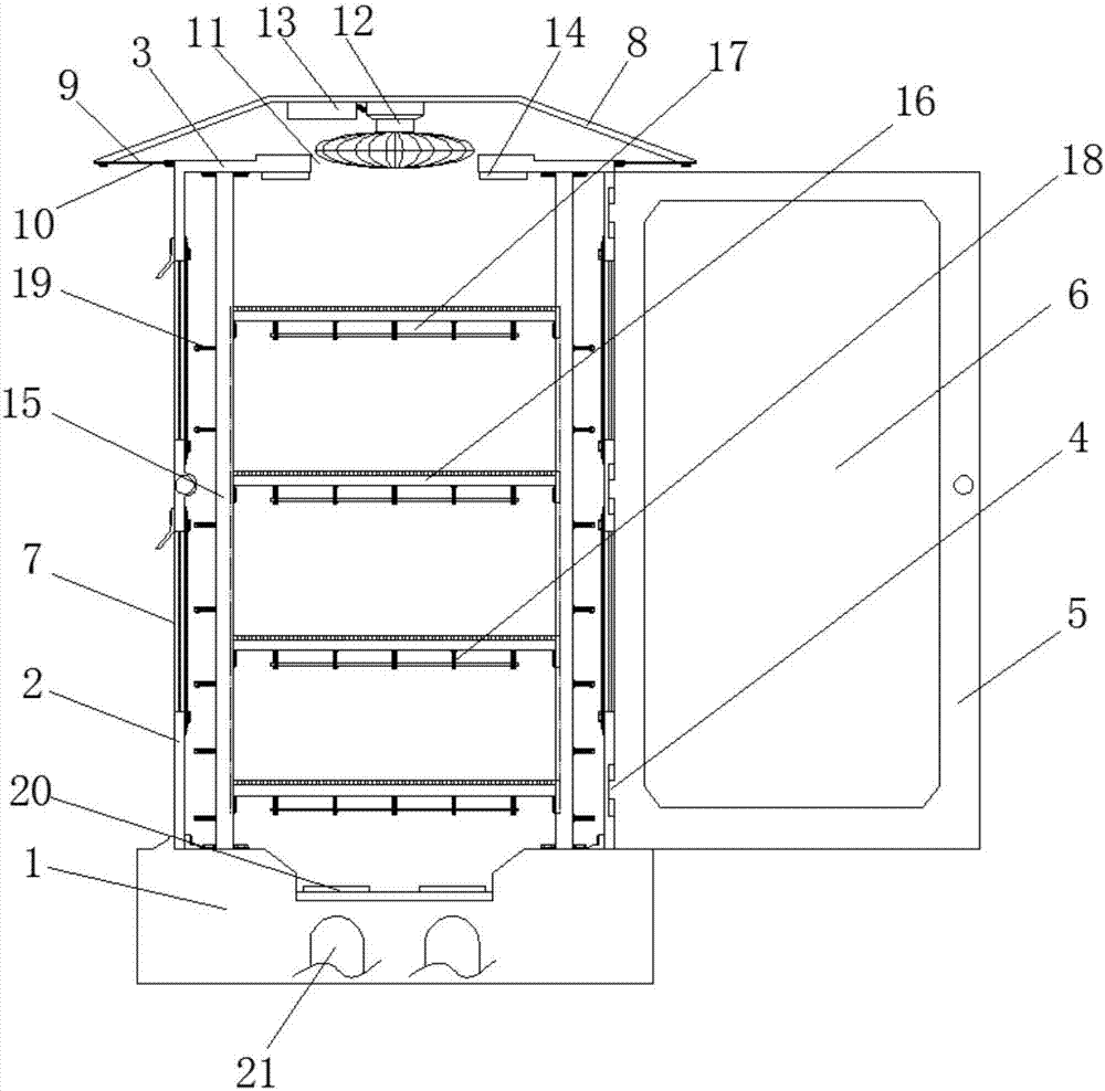
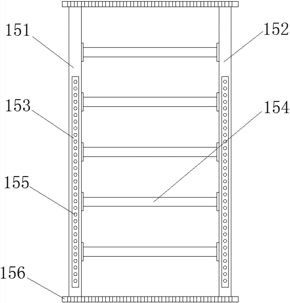
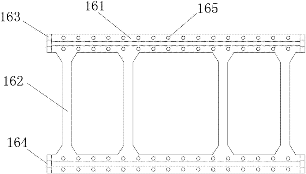
[0018] see Figure 1-4 , a communication system information exchange installation cabinet, including a base 1, a cabinet body 2 installed on the top of the base 1, and a top plate 3 integrally formed on the top of the cabinet body 2, a cabinet door 5 is installed on the right side of the front of the cabinet body 2 through a hinge 4, the A transparent plastic hard board 6 is installed in the middle of the cabinet door 5, and two heat dissipation windows 7 are ...


PUM


Abstract

The invention discloses an installing cabinet for a communication system information switch. The installing cabinet comprises a base, a cabinet body arranged at the top of the base, and a top board integrally formed at the top of the cabinet body. Two heat dissipation windows are arranged on both sides of the cabinet body and are located at positions, close to the top and the bottom, of the two sides of the cabinet body respectively. The middle of the top board is provided with a through hole. The top of the top board is provided with a top cover. The bottoms of both sides of the top cover are provided with air inlets. Dust filters are installed on the outsides of the air inlets and the inner sides of the heat dissipation windows. A blower fan is installed on the top of the top cover at a position corresponding to the through hole on the top board. By installing the blower fan and a blower fan controller in the top cover on the top of the top board, and arranging temperature sensors on both sides of the through hole which is arranged on the top board at a position corresponding to the blower fan and in cooperation with the heat dissipation windows on both sides of the cabinet body, the cabinet has an automatic active cooling effect, replace traditional natural cooling, improves the cooling efficiency.

Description

technical field [0001] The invention relates to the technical field of communication system information equipment, in particular to a communication system information switch installation cabinet. Background technique [0002] In the communication system, Internet communication is one of the current mainstream communication channels in society. When the Internet is laid, information switches are usually used to disperse the information transmitted by the main line to each branch line. At present, the cabinets used to install information switches are usually It is an ordinary cabinet, and the installation structure of the switch in the cabinet is basically fixed and cannot be adjusted. The installation of the information switch is extremely compact, resulting in poor cooling effect of the cabinet as a whole. In addition, the installation cabinet currently used for information switches in network communication systems, its The internal communication lines are intertwined and mi...

Claims


Application Information

Patent Timeline
Patent Type & Authority Applications(China)
IPC IPC(8): H05K7/20H05K5/02H05K7/14
CPCH05K5/0213H05K5/0217H05K5/0247H05K7/14H05K7/20145H05K7/20172H05K7/20209H05K7/2039
Inventor 康玮
Owner YANGTZE UNIVERSITY
Learn More