
Steaming cabinet

A technology for steaming cabinets and cabinets, applied in the field of steaming cabinets, can solve problems such as complex structures, and achieve the effects of high thermal efficiency, energy saving, and accelerated steam flow rate

Active Publication Date: 2017-11-10
山东东方方圆厨房设备有限公司
View PDF5 Cites 9 Cited by
  • Summary
  • Abstract
  • Description
  • Claims
  • Application Information

AI Technical Summary

Problems solved by technology

[0003] In order to solve the above-mentioned technical problems of complex structure and energy consumption reduction, the present invention provides a steamer

Method used


Image

  • Steaming cabinet
  • Steaming cabinet
  • Steaming cabinet

Examples


Embodiment

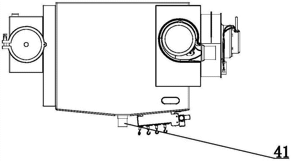
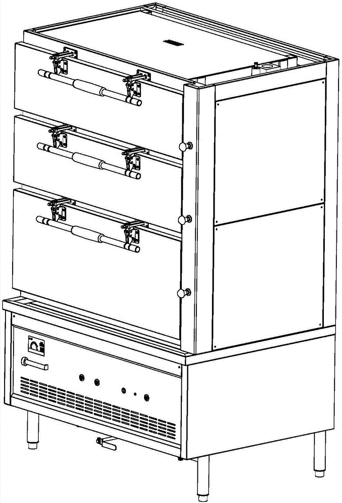
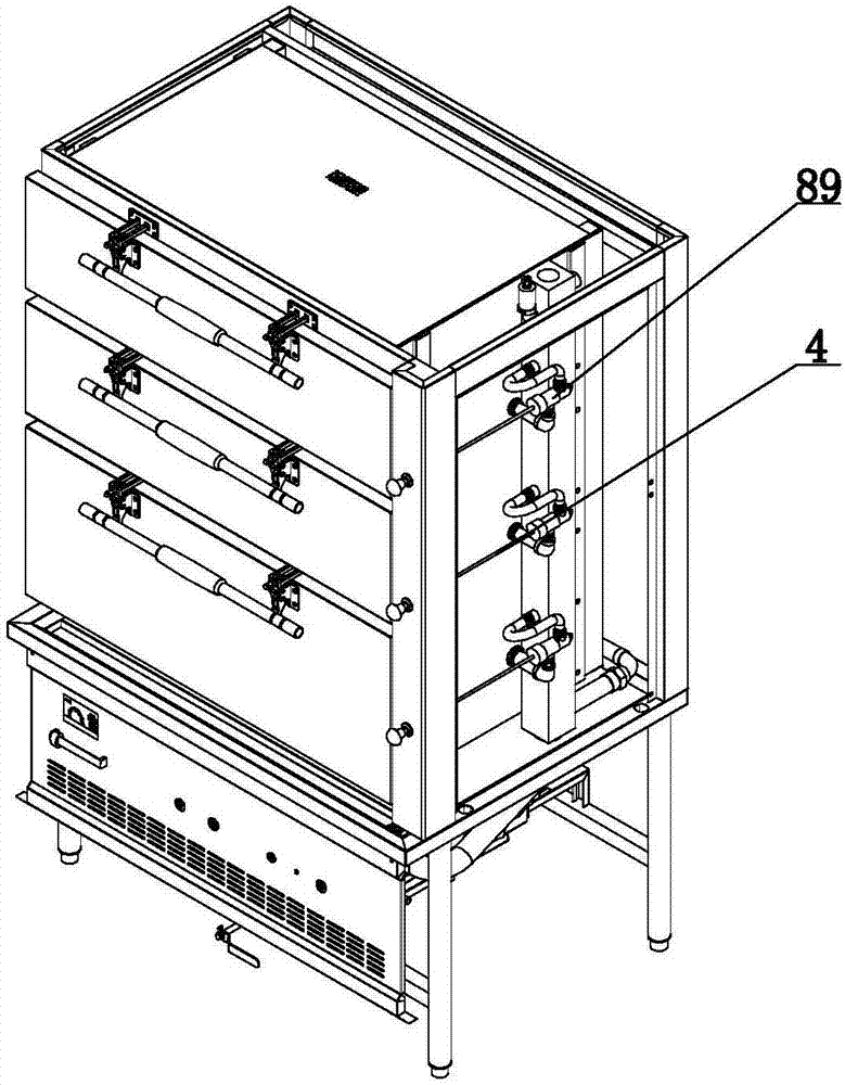
[0031] Such as figure 1 , 2, 3, 4, 5, 6, 7, 8, 9, 10, 11, 25 shown in the steam cabinet, including cabinet, water tank, burner, electrical box and power supply structure, the upper part of the cabinet is provided with a storage cabinet , the lower part of the cabinet is equipped with a water tank, the bottom of one side of the water tank is hollowed out to form a combustion chamber, and a burner is arranged under the combustion chamber, the burner includes a fire row, and the fire row is located at the bottom of the water tank, and the DC brushless fan 12 and single The high-speed blower 9 and the DC brushless blower 12 are variable-frequency blowers to save electric energy. The DC brushless blower 12 discharges the gas generated by combustion to the hollow pipe 81 of the steam pipe 2, and the inner chamber and the boiler connecting plate are arranged above the water tank 70, the inner chamber and the boiler connecting plate 70 communicate with the external pipe 80 of the SAI...

Embodiment 2

[0070] The difference between this embodiment and Embodiment 1 is the mode selection drive circuit. The mode selection drive circuit has four toggle switches, which can be combined into multiple modes. Each mode can choose a different gear switch type, manual or automatic mode, Different program settings are suitable for different devices.

Embodiment 3

[0072] The difference between this embodiment and Embodiment 1 is the gate control detection circuit. According to the signal sent by the gate control switch that several doors are in use, the large, medium and small fires are automatically selected. At the beginning, when the temperature is low, the fire is burned at the maximum , when the temperature reaches a certain level, the firepower is controlled by the number of doors used, and the specific parameters can be set by the program.


PUM


Abstract

The invention relates to the field of cooking heating equipment and especially relates to a steaming cabinet. The steaming cabinet comprises a cabinet body, a water tank, a combustor, an electric appliance box and a power source structure, wherein a storage cabinet is disposed on the upper part of the cabinet body; the water tank is disposed on the lower part of the cabinet body; the bottom on one side of the water tank is hollow, and a combustion room is formed; the combustor is disposed under the combustion room; the combustor comprises a fire row; the fire row is disposed on the bottom of the water tank; a DC brushless fan is disposed on the water tank; the water tank communicates with the storage cabinet; a temperature detection probe is disposed at a steam outlet of the storage cabinet; a main control computer panel, a heat dissipation fan, an igniter and an electromagnetic valve are disposed in the electric appliance box; the main control computer panel has or is connected to a water level controller; the heat dissipation fan, the igniter and the electromagnetic valve are connected to the main control computer panel; the igniter is connected to an ignition pin of the fire row; and the temperature detection probe, a fire row fire-detection pin, a water level detection probe and the main control computer panel are connected. The steaming cabinet disclosed by the invention has the beneficial effects that structure design is skillful; the whole product is mature and novel; noise is low; heat efficiency is high; energy sources are saved; and performance is good.

Description

technical field [0001] The invention relates to the field of cooking heating equipment, especially a steam cabinet. Background technique [0002] Steaming cabinets include electric steaming cabinets and gas steaming cabinets. Gas steaming cabinets are more popular with users because of the use of gas and taste. It is necessary to consider energy consumption and other issues, as well as reduce labor costs, to achieve intelligent adjustment, to avoid human negligence, resulting in water shortage of equipment, damage caused by dry burning of water, gas leakage caused by flame extinguishing, and carbon monoxide poisoning caused by insufficient combustion. There are great safety hazards in the use of such accidents, so a reasonable structural design is required to ensure the safety of the steps with preventive measures, and it can also control and adjust, improve efficiency, reduce energy consumption, and improve benefits. Contents of the invention [0003] In order to solve t...

Claims


Application Information

Patent Timeline
IPC IPC(8): A47J27/16A47J36/00A47J36/30
CPCA47J27/16A47J36/00A47J36/30
Inventor 左向涛
Owner 山东东方方圆厨房设备有限公司
Learn More