

LED module and method for pouring glue on surface of LED module
An LED module and glue filling technology, which is applied to devices and coatings for coating liquid on the surface, can solve the problems of high cost, cumbersome process, unsatisfactory glue filling process effect, etc., and achieves low cost and simple method. Line, smooth surface effect
- Summary
- Abstract
- Description
- Claims
- Application Information
AI Technical Summary
Problems solved by technology
Method used
Image

Examples
Embodiment 1
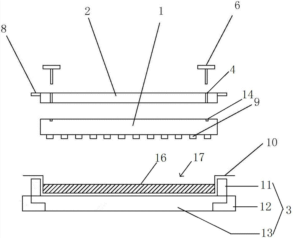
[0059] A glue filling mold is used to glue the light-emitting diode 9 on the surface of the LED module 1. The structure of the glue filling mold is as follows: figure 1 As shown, it includes the first mold part 2 and the second mold part 3 arranged up and down, the LED module 1 is fixed on the bottom of the first mold part 2, and the top of the second mold part 3 is provided with a cavity for containing glue 16 17. The bottom surface of the cavity 17 is a horizontal plane; a support plate 8 is provided on the left and right sides of the first mold part 2, and a horizontal bead is provided on the side of the LED module 1 (not marked in the figure). The four corners of the LED module 1 are provided with four first threaded holes 14, and the four corners of the first mold part 2 are provided with four mounting holes 4 corresponding to the positions of the first threaded holes 14; And the LED module 1 passes through the mounting hole 4 through the four bolts 6 and cooperates with ...
Embodiment 2
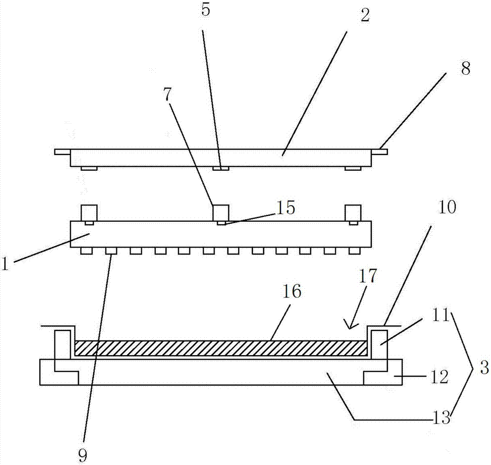
[0061] A glue filling mold is used to glue the light-emitting diode 9 on the surface of the LED module 1. The structure of the glue filling mold is as follows: figure 2 As shown, it includes the first mold part 2 and the second mold part 3 arranged up and down, the LED module 1 is fixed on the bottom of the first mold part 2, and the top of the second mold part 3 is provided with a cavity for containing glue 16 17. The bottom surface of the cavity 17 is a horizontal plane; a support plate 8 is provided on the left and right sides of the first mold part 2, and a horizontal bead is provided on the side of the LED module 1 (not marked in the figure). Four second threaded holes 15 are arranged in the middle of the four sides of the LED module 1, and magnets 7 are threaded inside each second threaded hole 15. The four magnetic parts 5; the four magnetic parts 5 are suction-connected with the four magnets 7 so that the first mold part 2 is fixedly connected to the LED module 1 .
Embodiment 3
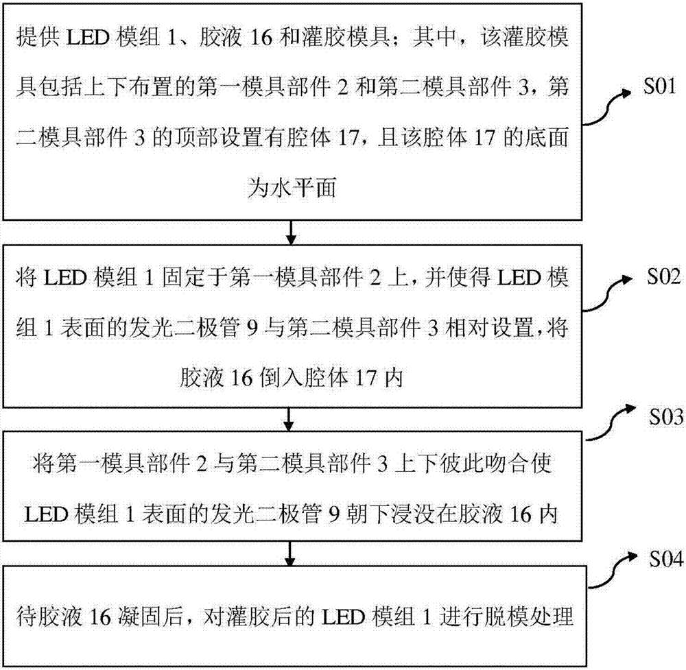
[0063] A method for pouring glue on the surface of an LED module, comprising the steps of:
[0064] S31: Provide the LED module 1, the glue solution 16 and the glue filling mold in the embodiment 1 / embodiment 2.
[0065] S32 : Fix the LED module 1 on the first mold part 2 , make the light emitting diode 9 on the surface of the LED module 1 opposite to the second mold part 3 , and pour the glue 16 into the cavity 17 .
[0066] S33: Fitting the first mold part 2 and the second mold part 3 vertically together so that the light emitting diode 9 on the surface of the LED module 1 is immersed in the glue solution 16 facing downward, and then vacuum defoaming treatment is performed.
[0067] S34: After the glue solution 16 is solidified, perform a demoulding process on the glue-filled LED module 1 .
PUM
 Abstract
Description
Claims
Application Information