A card position-driven translational wire harness cutting machine based on rotational speed detection

A speed detection and cutting machine technology, applied in metal processing equipment, metal processing, manufacturing tools, etc., can solve problems affecting work efficiency, etc., and achieve the effect of improving wire harness cutting efficiency, efficient and stable wire harness cutting

Active Publication Date: 2018-11-09
南通北外滩建设工程有限公司
View PDF7 Cites 0 Cited by
  • Summary
  • Abstract
  • Description
  • Claims
  • Application Information

AI Technical Summary

Problems solved by technology

[0002] The wiring harness is the wire used to transmit electric energy and signals. With the continuous improvement of the quality of modern life, the transmission of electric energy, signal and information is ubiquitous. In the actual application of the wire rod, it needs to be cut according to the actual use, but the existing wire rod cutting is all manual operation, that is, the length of the wire bundle is measured manually, the cutting position is marked, and finally the cutting is carried out according to the position of the cutting mark to obtain the actual Application of wire, this method greatly affects the actual work efficiency

Method used


Image

  • A card position-driven translational wire harness cutting machine based on rotational speed detection

Examples


Embodiment Construction

[0015] The specific implementation manners of the present invention will be further described in detail below in conjunction with the accompanying drawings.

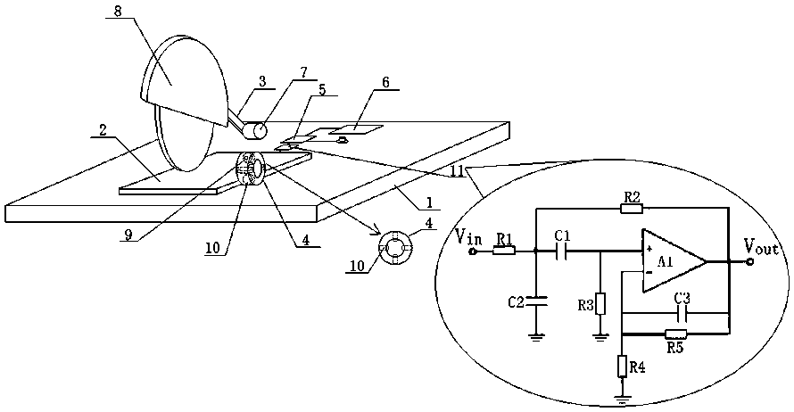
[0016] Such as figure 1As shown, the present invention designs a clamp-driven translational wire harness cutting machine based on rotation speed detection, which is used to cut a specified type of wire harness, including a base 1, a riser plate 2, a rotating arm 3, and a clamping sleeve 4 , a speed sensor 9 and a control module 5, and a power supply 6 connected to the control module 5, a rotating motor 7, an electronically controlled rotary cutterhead 8, a control input device, a filter circuit 11 and at least four electrically controlled drive wheels 10, the rotating speed The sensor 9 is connected to the control module 5 through the filter circuit 11; wherein, the power supply 6 supplies power to the rotating motor 7, the electric control rotary cutter head 8, the control input device, and each electric control drive w...


PUM


Abstract

The invention relates to a clamping-position driven horizontally moving wire cutting machine based on rotational speed detection. A brand new structural design is adopted and an electromechanical hybrid electrically controlled structure is introduced, and a built-in clamping casing pipe (4) of each electrically controlled drive wheel (10) is designed based on the application of an electrically controlled rotary cutter (8); a fully automatic cutting process is achieved through the fixing of a clamping position for a wire harness and the function of transporting to the electrically controlled rotary cutter (8) through the clamping casing pipe (4); a rotation speed sensor (9) is introduced for the electrically controlled drive wheels (10), based on a specifically designed filter circuit (11); according to the perimeter of the electrically controlled drive wheels (10) and in combination with the distance from the upper surface contact points of an upper cutter of the electrically controlled rotary cutter (8) and a padding plate (2) to the clamping casing pipe (4), the length of the wire harness going through the upper surface contact points of the cutter and the padding plate (2) is acquired in real time; accordingly, the intelligent control of a rotating motor for controlling the cutting action of the electrically controlled rotary cutter (8) is achieved, accurate cutting is achieved for the wire harness, and the cutting efficiency of the wire harness can be effectively improved.

Description

technical field [0001] The invention relates to a clamping drive translational wire harness cutting machine based on rotational speed detection, which belongs to the technical field of wire harness wiring. Background technique [0002] The wiring harness is the wire used to transmit electric energy and signals. With the continuous improvement of the quality of modern life, the transmission of electric energy, signal and information is ubiquitous. In the actual application of the wire rod, it needs to be cut according to the actual use, but the existing wire rod cutting is all manual operation, that is, the length of the wire bundle is measured manually, the cutting position is marked, and finally the cutting is carried out according to the position of the cutting mark to obtain the actual The application of wire material greatly affects the actual work efficiency. Contents of the invention [0003] The technical problem to be solved by the present invention is to provide ...

Claims


Application Information

Patent Timeline
Patent Type & Authority Patents(China)
IPC IPC(8): B21F11/00B21F23/00B21C51/00
CPCB21C51/00B21F11/00B21F23/005
Inventor 黄敏
Owner 南通北外滩建设工程有限公司
Why Eureka
Try Eureka