Synchronizer gear ring inner ring machining composite clamp

A synchronizer gear ring and fixture technology, which is used in manufacturing tools, metal processing equipment, metal processing machinery parts, etc., can solve the problem that the workpiece cannot be guaranteed to meet the coaxiality, the dimensions between processes cannot be effectively connected, and the order scheduling is difficult to track, etc. problems, to achieve the effect of canceling intermediate work-in-process inventory, facilitating processing, and preventing interference

Pending Publication Date: 2017-11-10
WUHAN KYOWA SYNCHRONIZER RING
View PDF6 Cites 13 Cited by
  • Summary
  • Abstract
  • Description
  • Claims
  • Application Information

AI Technical Summary

Benefits of technology

This patented technology allows robots to hold and process thin metal plating (FPM), allowing them to accurately locate and align different parts during manufacturing processes without being affected or damaged from external forces such as gravity. It also ensures accurate circular shape of the FPM's internal structure while loading it onto an industrial robotic arm called CNC machining tools.

Problems solved by technology

This technical problem addressed by this patented method relates to improving the accuracy and efficiency of manufacturing internal combustion engines with synchronizers due to variations caused from different factors such as machine tool wear on parts made of materials like chrome plating (chrome), thermal expansion differences affects precision levels across various components, and other issues related to ensured proper alignment and assembly.

Method used


Image

  • Synchronizer gear ring inner ring machining composite clamp
  • Synchronizer gear ring inner ring machining composite clamp
  • Synchronizer gear ring inner ring machining composite clamp

Examples


Embodiment Construction

[0037] The present invention will be further described below in conjunction with specific examples.

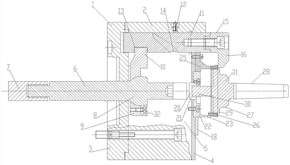
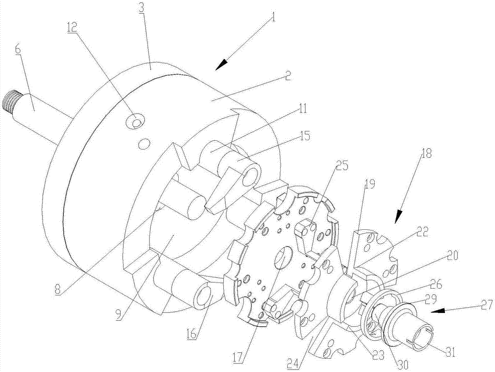
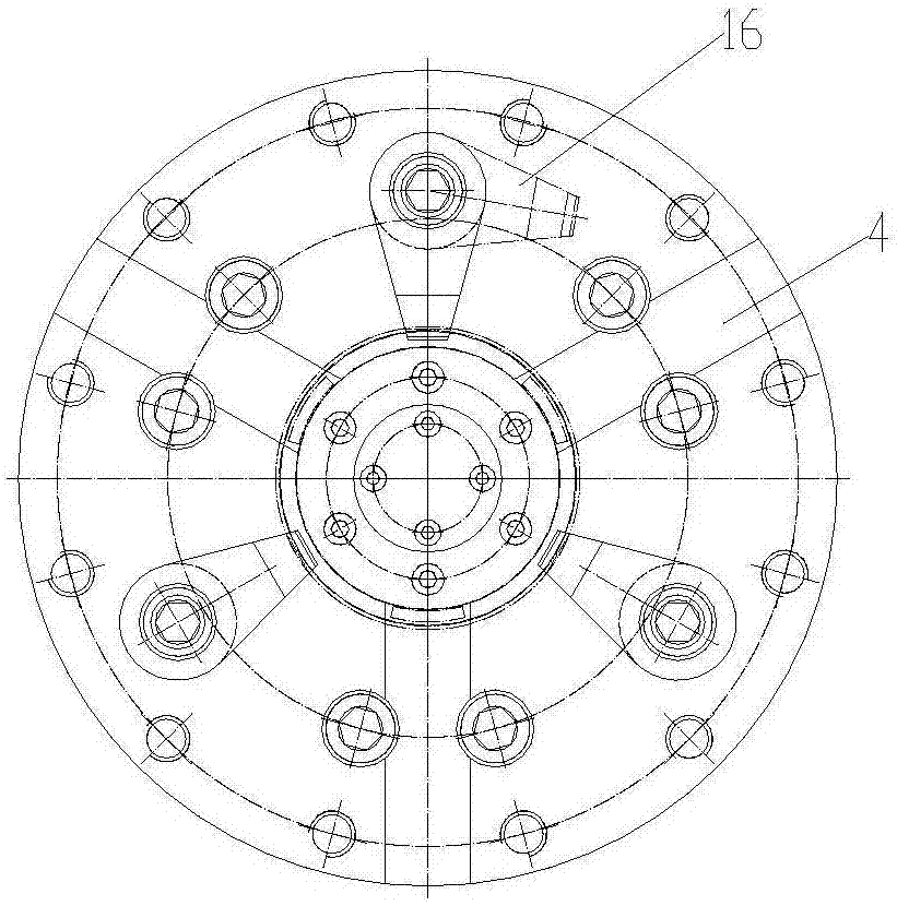
[0038] Such as Figure 1-Figure 7As shown, a compound fixture for processing the inner ring of the synchronizer gear ring includes a hollow chuck 1, and the hollow chuck 1 includes a chuck side wall 2, a chassis 3, and a connecting plate 4; the chassis 3 and the connecting plate 4 are respectively located on the side of the chuck The two ends of the cavity 5 formed around the wall 2; the outer surface of the chassis 3 is fixed to the machine tool, and the center part of the chassis 3 is horizontally penetrated with a chuck tie rod 6, and one end of the chuck tie rod 6 is connected to one end of the main shaft tie rod 7 through a nut, and the main shaft tie rod 7 is located outside the cavity 5, and the other end is connected with the machine tool; the middle part of the chuck rod 6 is connected with a floating ball post 8, which is a cylinder formed by the middle part of the r...


PUM


Abstract

The invention discloses a synchronizer gear ring inner ring machining composite clamp which comprises a hollow chuck. A chuck pull rod linkage mechanism is arranged in the hollow chuck. The linkage mechanism drives workpiece pull rods in the hollow chuck. Rotary clamp grooves are formed in the workpiece pull rods and achieve autoroatation under the action of limiting pins so as to drive workpiece press plates on the workpiece pull rods to rotate to fix and loosen a workpiece. A workpiece inner cone top disc and a centre matched with the hollow chuck are designed on a machine tool tailstock to carry out inner ring axial and radial locating of the workpiece. According to the clamp, synchronizer gear ring inner ring clamping machining forming can be achieved at a time; on the premise of guaranteeing the requirements of synchronizer gear ring inner ring inner face and outer face coaxiality, roundness, bounce machining and the like, automatic mechanical arm feeding is facilitated, and meanwhile precise machining of synchronizer gear ring inner rings is achieved; the problem about side connection between procedures is avoided; the machining efficiency is high; the middle work-in-process inventory is cancelled; orders are easy to track; the transfer time is short; and the existing one-piece flow development tendency is met.

Description


Claims


Application Information

Patent Timeline
Owner WUHAN KYOWA SYNCHRONIZER RING
Why Eureka
Try Eureka