System for reverse crankcase ventilation during boosted engine operation

A ventilation system and engine technology, applied in crankcase ventilation, engine components, combustion engines, etc., can solve problems such as pollution, reduced engine exhaust and air intake performance, engine knocking, etc.

Inactive Publication Date: 2017-11-10
FORD GLOBAL TECH LLC
View PDF6 Cites 8 Cited by
  • Summary
  • Abstract
  • Description
  • Claims
  • Application Information

AI Technical Summary

Problems solved by technology

Sludge is a problem in itself and causes varnish and deposits to form on engine components such as on the back of poppet valves, thereby reducing engine exhaust suction (performance) and acting as a thermal insulator for valves, causing them to overheat and/or or engine knock
In addition, the

Method used


Image

  • System for reverse crankcase ventilation during boosted engine operation
  • System for reverse crankcase ventilation during boosted engine operation
  • System for reverse crankcase ventilation during boosted engine operation

Examples


Embodiment Construction

[0029]Persons skilled in the art will appreciate that various features of an embodiment illustrated and described with reference to any one figure can be combined with features illustrated in one or more other figures to produce not specifically described features. Alternative embodiments illustrated or described. The combinations of features described provide representative embodiments of typical applications. However, various combinations and modifications of the features consistent with the teachings of the present disclosure may be contemplated for particular applications and implementations. Regardless of whether it is explicitly illustrated or described, those skilled in the art should be able to think of similar applications or implementations.

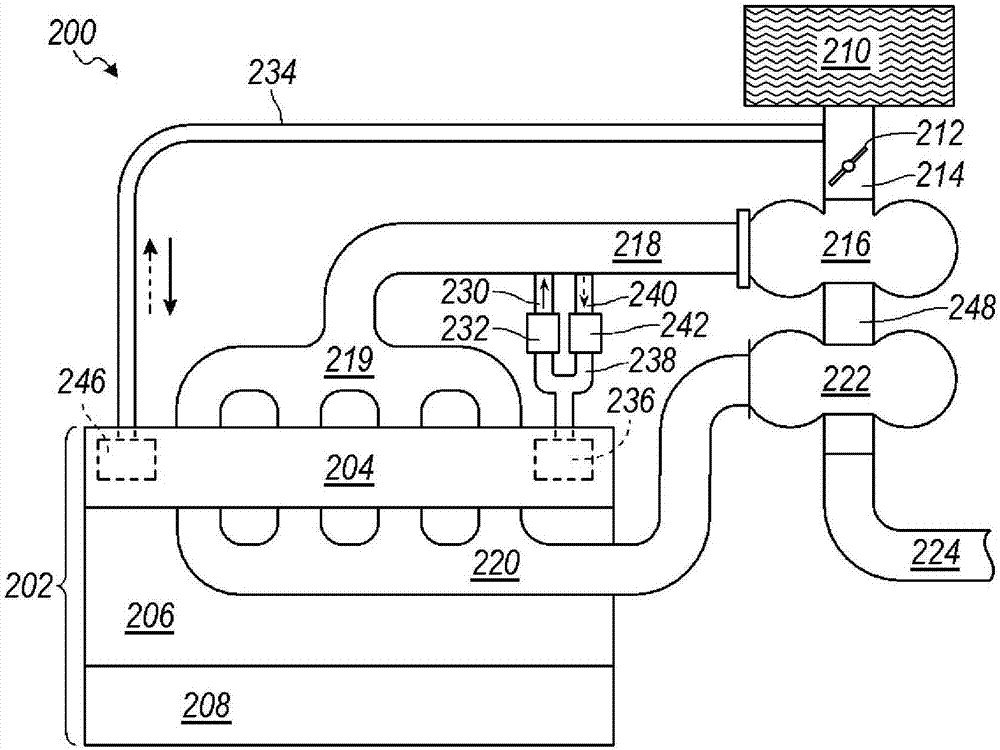
[0030] figure 2 One embodiment of a PCV system for an inline supercharged engine is shown. The engine system 200 has an internal combustion engine 200 having a cylinder head 204 coupled to an engine block 206 having an oil p...


PUM


Abstract

The invention relates to a system for reverse crankcase ventilation during boosted engine operation. Positive crankcase ventilation (PCV) systems have been employed on naturally-aspirated engines for over half a century. The gases in the crankcase exit the engine into the engine intake due to the slightly elevated pressure in the crankcase. Flow is controlled via a PCV valve in a PCV duct. In pressure-charged engines, PCV flow stops when pressure in the intake exceeds that of the crankcase. Such stagnation leads to sludging and deposit formation. According to an embodiment of the disclosure, reverse flow through the system is allowed by installing a second PCV valve in parallel with the normally-provided PCV valve, with the second PCV valve allowing an opposite direction of flow. Oil separators are provided on both PCV ducts to and from the engine to remove oil from blowby gases for flow in either direction.

Description

technical field [0001] The present disclosure relates to venting the engine crankcase during engine boost operation. Background technique [0002] Reciprocating internal combustion engines use piston rings so that the high-pressure combustion gases in the cylinders cannot easily leak into the crankcase. In a properly assembled piston-liner system, a small fraction of less than 1% of gas does leak out of the combustion chamber through the piston rings and ring gaps. These gases are combustion products of partial combustion and contain unburned fuel as well as reaction components of the partially burned fuel mixed with air. The first emission control measure applied to vehicle internal combustion engines in the 1960s was the positive crankcase ventilation (PCV) system, which is commonly used today. [0003] As shown in FIG. 1 , an engine system 100 with a PCV system is shown as a naturally aspirated engine 102 . The engine 102 has: a cylinder head 104 with a rocker cover (n...

Claims


Application Information

Patent Timeline
IPC IPC(8): F01M13/00F01M13/04F02M35/10
CPCF01M13/00F01M13/0011F01M13/04F02M35/10157F02M35/10222F01M2013/0044F01M13/023F02B33/00F02M25/06Y02T10/12F01M13/028
Inventor R·德维韦迪T·A·卡帕夫
Owner FORD GLOBAL TECH LLC
Why Eureka
Try Eureka