
Backlight module and liquid crystal display

A liquid crystal display and backlight module technology, which is applied in the fields of instruments, optics, nonlinear optics, etc., can solve the problems of affecting the improvement of LCD display quality, short light transmission path, uneven brightness of the backlight module 20, etc., and achieves great improvement. Viewing angle display quality, the effect of improving uniformity

Inactive Publication Date: 2017-11-10
TCL CHINA STAR OPTOELECTRONICS TECH CO LTD
View PDF8 Cites 10 Cited by
  • Summary
  • Abstract
  • Description
  • Claims
  • Application Information

AI Technical Summary

Problems solved by technology

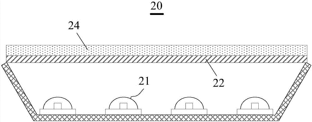
However, in the backlight module 20 based on this technology, there is more blue light in the area directly above the light source 21, and the light transmission path is shorter, and the number of times the blue light is scattered is less, resulting in the LCD in the area directly above the light source 21. On the other hand, in the area directly above the light source 21, such as between two adjacent light sources 21, there is less blue light, and the light transmission path is longer, and the blue light is scattered more times, causing the LCD to turn yellow in this area, thus making the backlight The brightness of the light emitted by the module 20 is uneven, and mura (uneven display brightness) is prone to occur, which affects the improvement of the display quality of the LCD when it is displayed at a large viewing angle

Method used


Image

  • Backlight module and liquid crystal display
  • Backlight module and liquid crystal display
  • Backlight module and liquid crystal display

Examples


Embodiment Construction

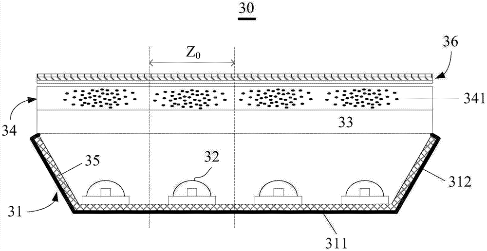
[0015] The main purpose of the present invention is: install a fluorescent film above the LED, and adjust the distribution density of the fluorescent particles in the fluorescent film, specifically, directly above the LED, the distribution density of the fluorescent particles is relatively large, and the number of times the blue light is scattered is relatively small. In the area directly above the LED, the distribution density of fluorescent particles is small, and the number of times blue light is scattered is less. By optimizing the distribution density of fluorescent particles, the number of times blue light is scattered in different areas tends to be the same, thus Improve the uniformity of the luminance of the backlight module, and improve the display quality of the LCD with a large viewing angle.

[0016] The following will clearly and completely describe the technical solutions of each exemplary embodiment provided by the present invention with reference to the accompan...


PUM


Abstract

The invention discloses a backlight module and a liquid crystal display. The backlight module comprises a back plate, a light source arranged on the back plate, and a fluorescent film arranged above the light source, and fluorescent particles are distributed in the fluorescent film and are used for scattering light emitted by an LED, wherein the distribution density of the fluorescent particles gradually decreases from the center to the periphery of an area in the area of each LED corresponding to the fluorescent film. Based on the backlight module, the uniformity of brightness of emergent light of the backlight module is improved, and the large viewing angle display quality of an LCD is improved.

Description

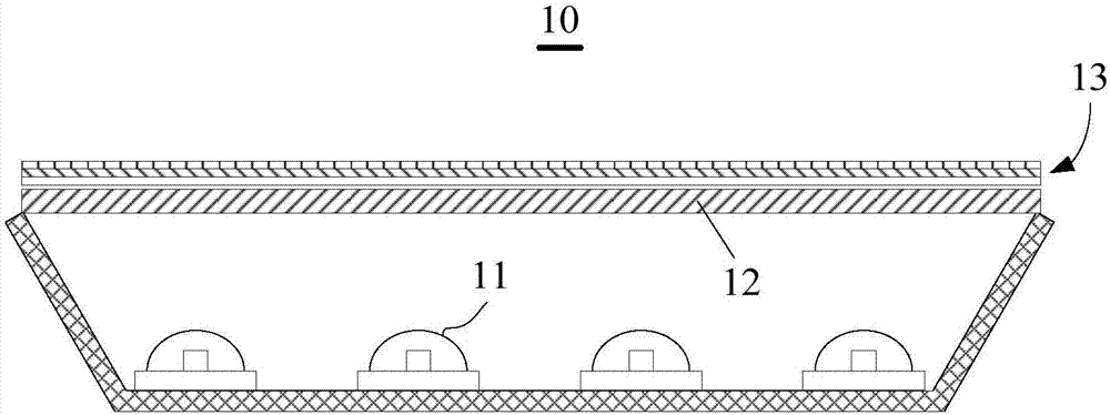
technical field [0001] The invention relates to the display field, in particular to a backlight module and a liquid crystal display. Background technique [0002] The backlight module usually uses LED (Light Emitting Diode, light emitting diode) as the light source, for example figure 1 As shown, in the direct-lit backlight module 10, the light emitted by the light source 11 is diffused by a diffuser plate (Diffuser plate, DP) 12 and transmitted upwards, and then diffused and integrated by various optical films 13 to form a uniform Surface light source, and provided to the liquid crystal panel of LCD (Liquid Crystal Display, liquid crystal display). Wherein, although the prism sheet (BEF, Brightness Enhancement Film) in the optical film 13 can increase the display brightness of the LCD, its light concentrating effect will reduce the display viewing angle of the LCD, for example, at 1 / 3 brightness (1 / 3 of the brightness of the front viewing angle). 3) When the display viewi...

Claims


Application Information

Patent Timeline
Patent Type & Authority Applications(China)
IPC IPC(8): G02F1/13357
CPCG02F1/133603G02F1/133606G02F1/133614
Inventor 常建宇张简圣哲苏赞加
Owner TCL CHINA STAR OPTOELECTRONICS TECH CO LTD
Learn More