
CT (Computed Tomography) helical scanning image reconstruction method and device

A technology of helical scanning and image reconstruction, applied in image enhancement, image analysis, image data processing, etc., can solve the problems of artifacts, uneven distribution of helical scanning data, etc., and achieve the effect of reducing artifacts

Active Publication Date: 2017-11-10
SHANGHAI UNITED IMAGING HEALTHCARE
View PDF5 Cites 1 Cited by
  • Summary
  • Abstract
  • Description
  • Claims
  • Application Information

AI Technical Summary

Problems solved by technology

[0006] The present invention solves the problem of artifacts caused by uneven distribution of helical scan data in the existing CT helical scan image reconstruction process

Method used


Image

  • CT (Computed Tomography) helical scanning image reconstruction method and device
  • CT (Computed Tomography) helical scanning image reconstruction method and device
  • CT (Computed Tomography) helical scanning image reconstruction method and device

Examples


Embodiment 1

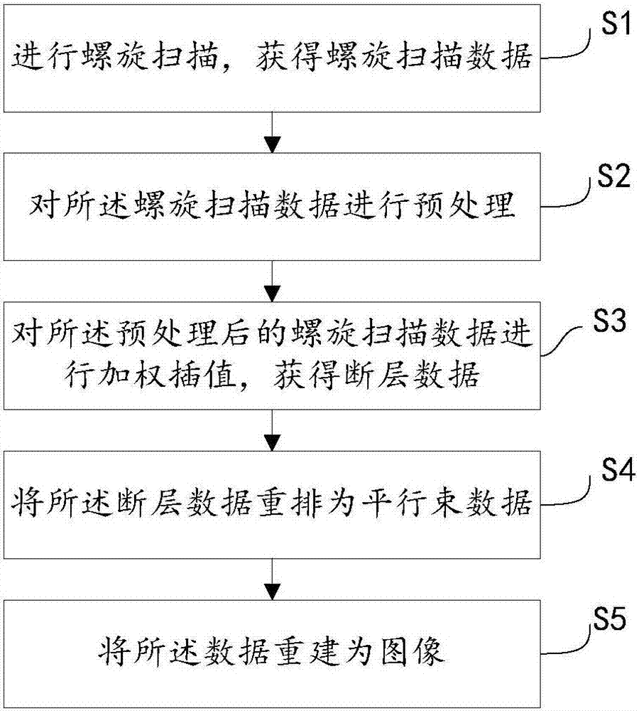
[0051] Such as Figure 4 As shown, the helical scan image reconstruction method of an embodiment of the present invention includes the following steps:

[0052] Step S401 is executed to perform a spiral scan to obtain spiral scan data.

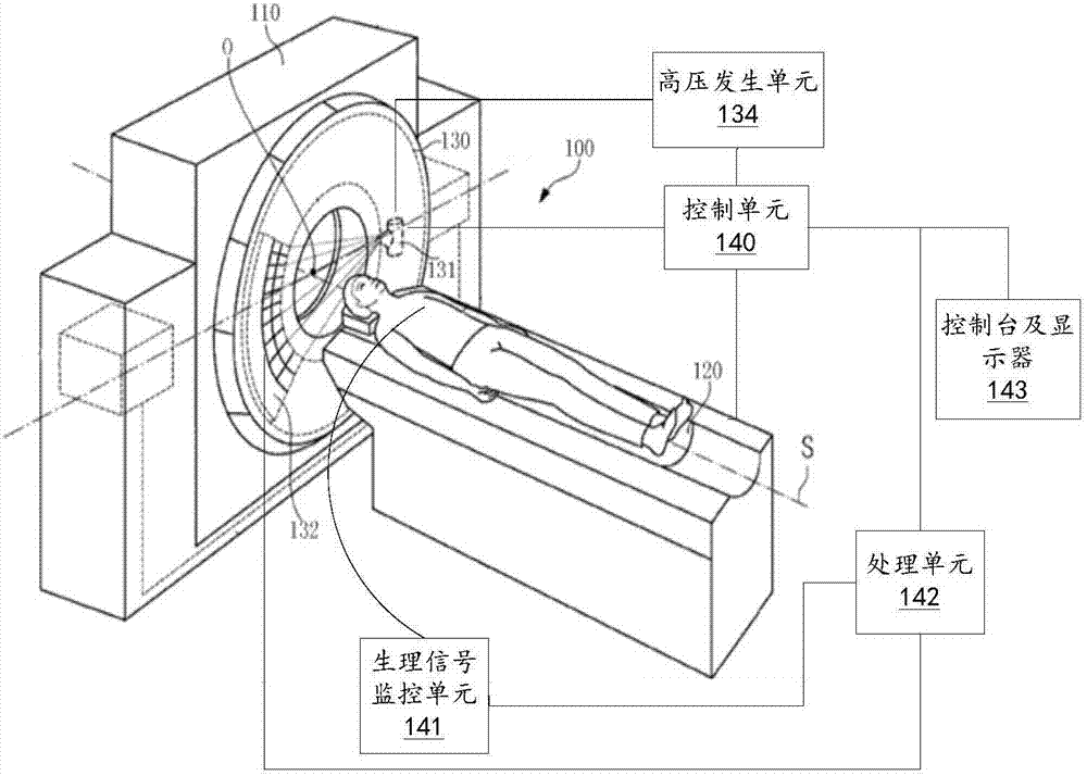
[0053] The spiral scan can be made by figure 1 The illustrated computer tomography system 100 is executed, and the spiral scan data can be collected by the X-ray detector 132.

[0054] Optionally, the obtained spiral scan data can also be preprocessed.

[0055] Step S402 is performed to determine the center and thickness of the reconstructed image, and determine the helical scan data range involved in reconstruction according to the center and thickness of the image.

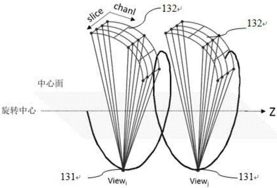
[0056] Figure 5 Is the projection diagram of the spiral scan data on the central plane, such as Figure 5 As shown, the spiral scan data can be regarded as the projection of X-rays on the central plane. The X-ray beam of each view forms a series of ray projections arranged along the z-ax...

Embodiment 2

[0069] Figure 7 Is a flowchart of the CT spiral scan image reconstruction method of this embodiment, such as Figure 7 As shown, steps S701, S702, and S703 of the CT spiral scan image reconstruction method of this embodiment are respectively the same as steps S401, S402, and S403 of the first embodiment; steps S706 and S707 of this embodiment are respectively the same as step S404 of the first embodiment , S405 is the same, so I won’t repeat it here. The difference is that the spiral scan data weighting factor in the spiral scan image reconstruction method of this embodiment also includes a second weighting factor. Therefore, this embodiment has more steps S704 and S705 than the first embodiment.

[0070] Step S704: Calculate a second weighting factor, where the second weighting factor is related to the distance of the helical scan data from the center of the image.

[0071] Preferably, a larger second weighting factor is used for the spiral scan data located near the center of th...


PUM


Abstract

The invention puts forward a CT (Computed Tomography) helical scanning image reconstruction method, which comprises the following steps that: carrying out helical scanning to obtain helical scanning data; obtaining a helical scanning data weighting factor, wherein the helical scanning data weighting factor comprises a first weighting factor, the first weighting factor relates to the density of the helical scanning data in a z-axis direction, and the z-axis direction is the rotation axis direction of the helical scanning; according to the weighting factor, carrying out interpolation on the helical scanning data to obtain segment data; and reconstructing the segment data into an image. By use of the helical scanning image reconstruction method, the distribution nonuniformity of the helical scanning data in the z-axis direction is considered in a weighted interpolation process, the first weighting factor related to the density of the helical scanning data in the z-axis direction is used for weighting the helical scanning data, and image artifacts can be effectively reduced. In addition, the invention also puts forward a CT helical scanning image reconstruction device.

Description

【Technical Field】 [0001] The invention relates to the technical field of computer tomography (CT, Computed Tomography), in particular to a CT spiral scan image reconstruction method and device. 【Background technique】 [0002] Computed Tomography (CT) uses X-rays to scan specific parts of the human body at a certain thickness. Since different human tissues have different X-ray absorption capabilities, a computer can be used to reconstruct tomographic images. [0003] At present, the two-dimensional spiral reconstruction method is a common CT spiral scan image reconstruction method. The principle is based on the spiral scan data obtained by the CT spiral scan first to obtain the tomographic data of the desired image plane through interpolation, and then to reconstruct the tomographic image Therefore, the key to the two-dimensional spiral reconstruction method lies in the interpolation method. [0004] In actual scanning, the pitch of CT spiral scan can be adjusted, and different scan ...

Claims


Application Information

Patent Timeline
IPC IPC(8): G06T11/00
CPCG06T11/005G06T2207/10081G06T2207/10104
Inventor 王鑫
Owner SHANGHAI UNITED IMAGING HEALTHCARE
Learn More