
Experimental device for verifying collision of horizontal projectile motion and free fall in sky

A technology of free fall and experimental device, which is applied in the direction of educational appliances, instruments, teaching models, etc., can solve the problems of two balls falling far apart, unfavorable comparison, and poor experimental effect, so as to achieve convenient operation and use, improve demonstration effect, and help students participatory effect

Pending Publication Date: 2017-11-10
柯胜
View PDF5 Cites 0 Cited by
  • Summary
  • Abstract
  • Description
  • Claims
  • Application Information

AI Technical Summary

Problems solved by technology

Existing experimental demonstration instruments can observe the motion of flat throwing, but the trajectory of the collision is blurred, which cannot be well captured by students, let alone thoroughly study the law of flat throwing motion; at the same time, the existing experimental demonstration instruments The center is not very stable, the experimental effect is poor, and the two balls land far away, which is not conducive to comparison, and the effect is not good

Method used


Image

  • Experimental device for verifying collision of horizontal projectile motion and free fall in sky

Examples


Embodiment Construction

[0013] In order to fully explain the implementation of the present invention, the present invention will be further described below in conjunction with specific examples. The given examples are only used to explain the present invention, not to limit the scope of the present invention.

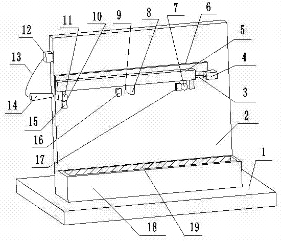
[0014] Such as figure 1 As shown, an experimental device for verifying the collision of a flat throw and a free fall in the air according to the present invention includes a base plate 1, a vertical plate 2 and a power drive device, and the vertical plate 2 is located on the base plate 1. The vertical plate 2 is provided with a plurality of support devices, and above the support device is provided with a clip 6 and a clip slot 5, the clip 5 can move left and right along the clip 6, and the clip 5 is provided with The clamping plate 8 matched with the supporting device, a flat throwing platform 10 and a plurality of mobile bayonets 9 are formed between the supporting device and the clamping pl...


PUM


Abstract

The invention relates to an experimental device for verifying the collision of horizontal projectile motion and free fall in the sky, and the device comprises a substrate, a vertical plate, and a power drive unit. The vertical plate is located on the substrate, and the vertical plate is provided with a plurality of supporting apparatuses. A clamping bar and a clamping groove are disposed above the supporting apparatuses, and the clamping groove can move left and right along the clamping bar. The clamping groove is provided with clamping board matched with the supporting apparatuses. One horizontal projectile platform and a plurality of moving bayonets are formed between the supporting apparatuses and the clamping board. The horizontal projectile platform is provided with a horizontal projectile steel ball which is used for verifying the horizontal projectile motion. The moving bayonets are provided with falling steel balls which are used for verifying the motion of free fall. The power drive unit is disposed in front of the clamping groove, and the power drive unit drives the clamping groove to move, thereby achieving the simultaneous moving of the horizontal projectile steel ball and the falling steel balls. The device provided by the invention can verify that the component motion of the horizontal projectile steel ball in the vertical direction is the motion of free fall after the horizontal projectile steel ball leaves a track. The device is simple in structure, is convenient to operate and use, and is vivid and visual in demonstration.

Description

technical field [0001] The invention belongs to the technical field of middle school physics and mechanics teaching and experimental instruments, and in particular relates to an experimental device for verifying the collision of a flat throw and a free fall in the air. Background technique [0002] Horizontal throwing motion is an important concept in the kinematics of middle school physics textbooks. In teaching, in order to let students understand that objects in flat throwing motion can be decomposed into uniform linear motion in the horizontal direction and vertical motion without considering the resistance. direction of free fall. Existing experimental demonstration instruments can observe the motion of flat throwing, but the trajectory of the collision is blurred, which cannot be well captured by students, let alone thoroughly study the law of flat throwing motion; at the same time, the existing experimental demonstration instruments The center is not very stable, the...

Claims


Application Information

Patent Timeline
Patent Type & Authority Applications(China)
IPC IPC(8): G09B23/10
CPCG09B23/10
Inventor 柯胜令狐荣鸿吴月先
Owner 柯胜
Learn More