Water-driven flue gas purification device for ship

A flue gas purification and purification device technology, applied in the field of flue gas purification, can solve problems such as smoke elimination and purification that are not suitable for ship fires, and achieve the effects of simple structure, convenient engineering overhaul and maintenance, and convenient access.

Inactive Publication Date: 2017-11-14
WUHAN UNIV OF SCI & TECH +1
View PDF6 Cites 1 Cited by
  • Summary
  • Abstract
  • Description
  • Claims
  • Application Information

AI Technical Summary

Problems solved by technology

[0006] To sum up, in terms of power and purification, the existing fire smoke suppression technology is not suitable for the smoke suppression and purification of ship fires

Method used


Image

  • Water-driven flue gas purification device for ship
  • Water-driven flue gas purification device for ship
  • Water-driven flue gas purification device for ship

Examples


Embodiment 1

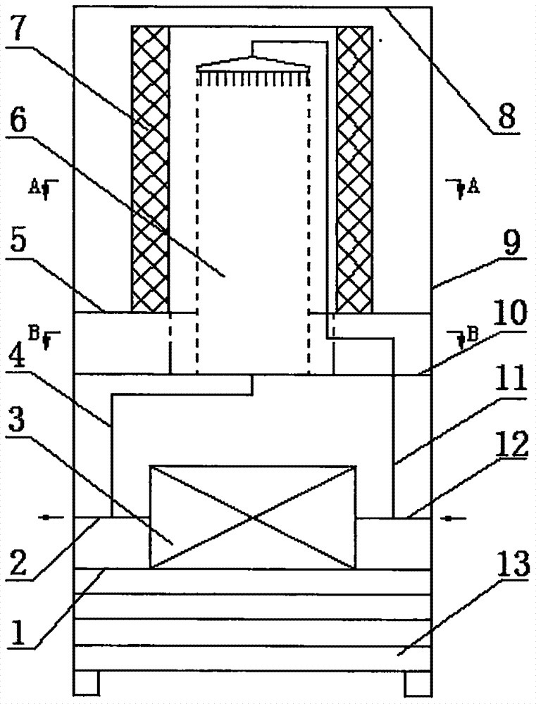
[0033] Disclosed is a device for purifying flue gas from ships driven by water. Such as figure 1 As shown, the purification device consists of a fan base plate 1, an outlet pipe 2, a water drive fan 3, a spray return pipe 4, a mounting plate 5, a spray unit 6, a filter cartridge 7, a wire mesh 8, a housing 9, and a bracket 10. It is composed of spray water supply pipe 11, water inlet pipe 12 and shutters 13.

[0034] Such as figure 1 As shown, one end of the water inlet pipe 12 is connected to the water inlet of the water-driven fan 3, and the other end passes through the housing 9 to externally connect to a high-pressure water source. One end of the water outlet pipe 2 is connected to the water outlet of the water-driven fan 3 , and the other end passes through the housing 9 . One end of the spray water supply pipe 11 is connected with the water inlet pipe 12 , and the other end is connected with the spray unit 6 . One end of the spray return pipe 4 is connected with the ...

Embodiment 2

[0042] Disclosed is a device for purifying flue gas from ships driven by water. Such as Figure 5 As shown, the purification device consists of a fan base plate 1, an outlet pipe 2, a water drive fan 3, a spray return pipe 4, a mounting plate 5, a spray unit 6, a filter cartridge 7, a wire mesh 8, a housing 9, and a bracket 10. It is composed of spray water supply pipe 11, water inlet pipe 12 and shutters 13. Except following technical parameter, all the other are with embodiment 1:

[0043] Such as Figure 5 , Figure 6 and Figure 7 As shown, the installation plate 5 is a flower plate, and the spray unit 6 and the filter cartridge 7 are multiple parallel structures. Each spray unit 6 is connected with a spray water supply pipe 11 and a spray return pipe 4 . Each spray water supply pipe 11 is connected with the water inlet pipe 12 , and each spray return water pipe 4 is connected with the water outlet pipe 2 . Each row of spray units 6 is fixed on the housing 9 through a...


PUM

PropertyMeasurementUnit
lengthaaaaaaaaaa
thicknessaaaaaaaaaa
heightaaaaaaaaaa

Abstract

The invention relates to a water-driven flue gas purification device for a ship. According to the technical scheme of the water-driven flue gas purification device, the purification device consists of a fan bottom plate (1), a water outlet pipe (2), a water-driven fan (3), a spray water return pipe (4), a mounting plate (5), a spray unit (6), a filter drum (7), a wire mesh (8), a shell (9), a bracket (10), a spray water supply pipe (11), a water inlet pipe (12) and a shutter (13). One end of the water inlet pipe (12) is connected with a water inlet opening of the water-driven fan (3); the other end of the water inlet pipe (12) passes through the shell (9) to be externally connected with a high-pressure water source; one end of the water outlet pipe (2) is connected with a water outlet opening of the water-driven fan (3); the other end of the water outlet pipe (2) passes through the shell (9). One end of the spray water supply pipe (11) is connected with the water inlet pipe (12); the other end of the spray water supply pipe (11) is connected with the spray unit (6); one end of the spray water return pipe (4) is connected with the spray unit (6); the other end of the spray water return pipe (4) is connected with the water outlet pipe (2). The water-driven flue gas purification device has advantages that the purification efficiency is high, a power source is reliable, the in-situ purification of flue gas from a fire disaster in a cabin can be realized, and the like.

Description

technical field [0001] The invention relates to the field of flue gas purification, in particular to a ship water flooding flue gas purification device. Background technique [0002] Ships are an important means of transportation for sailing or mooring in waters for transportation and operations. Once a fire accident occurs on a ship, it will cause serious casualties and property losses. Ship fires are different from conventional fires: it is difficult to fight fires, and the firefighting work is limited; based on self-rescue, it is difficult to obtain foreign aid; the ventilation effect in the cabin is poor, and the dense smoke is not easy to discharge (Zou Gaowan, Liu Shunlong, Zhou Yunji, etc. Research on fires in engine rooms in China Current status. Chinese Journal of Safety Science, 2004, 14(5): 76-79). [0003] Ship fires usually occur in the cabin, and it is difficult for people to escape, and the probability of death due to suffocation is extremely high. Therefor...

Claims


Application Information

Patent Timeline
Patent Type & Authority Applications(China)
IPC IPC(8): B01D50/00B01D46/52B01D53/04B63J2/02
CPCB01D46/525B01D53/04B63J2/02B01D2258/0283B01D2259/455B01D50/60
Inventor 向晓东朱青松钟杰常玉锋刘文文
Owner WUHAN UNIV OF SCI & TECH
Why Eureka
Try Eureka