Wing/blade air exciter

An exciter and gas technology, applied in the field of airfoil/blade gas exciters, can solve the problems of limited application of pipelines, inability to popularize practical applications, and high suction volume, to achieve large bonding area, increase circulation, and improve aerodynamics The effect of lift coefficient

Inactive Publication Date: 2017-11-14
青岛华创风能有限公司 +3
View PDF6 Cites 3 Cited by
  • Summary
  • Abstract
  • Description
  • Claims
  • Application Information

AI Technical Summary

Problems solved by technology

This method of slot suction is used on different airfoils and with different flaps to enhance lift, but the suction volume involved is too high (1% Q <3%), and cannot be popularized for practical application
Even though surface and multi-slot suction are still considered valuable methods for maintaining laminar flow at high Reynolds numbers, airfoils thinned to reduce drag at high speeds make it necessary to remove low-pressure external fluids. Larger piping applications within the more restricted

Method used


Image

  • Wing/blade air exciter
  • Wing/blade air exciter
  • Wing/blade air exciter

Examples


Embodiment Construction

[0022] The invention discloses a wing / blade gas exciter, which can be implemented by those skilled in the art by referring to the contents of this article and appropriately improving the components of the device. In particular, it should be pointed out that all similar substitutions and modifications are obvious to those skilled in the art, and they are all considered to be included in the present invention. The method and application of the present invention have been described through preferred embodiments, and the relevant personnel can obviously make changes or appropriate changes and combinations to the method and application described herein without departing from the content, spirit and scope of the present invention to realize and Apply the technology of the present invention.

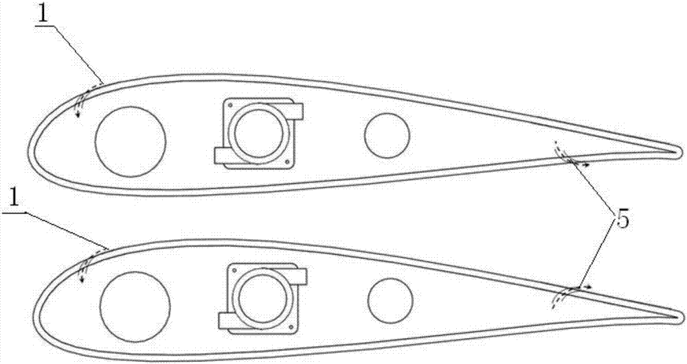
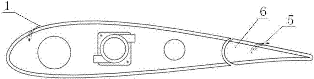
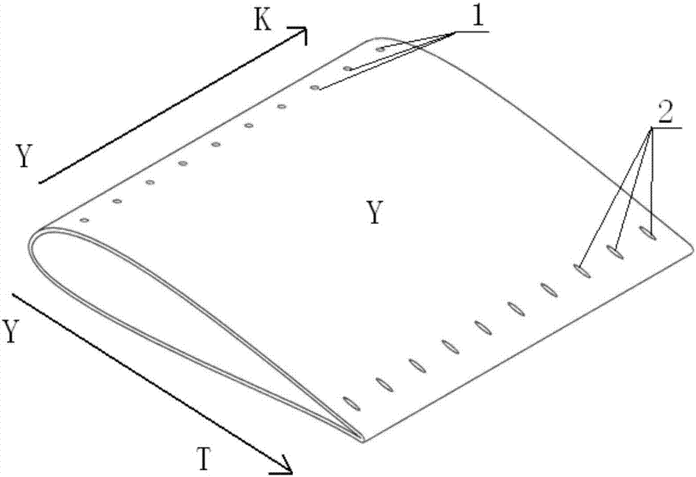
[0023] The present invention provides a wing / blade gas exciter, including a wing Y, and an air inlet 1, an air outlet 5, a first connecting pipe 2, a gas delivery driving device 3 and a second ...


PUM


Abstract

The invention belongs to the field of air exciters and discloses a wing/blade air exciter. The air exciter comprises a wing, air inlet holes, air outlet holes, first connecting pipelines, an air delivery driving device and second connecting pipelines, wherein the wing is provided with the air inlet holes, the air outlet holes, the first connecting pipelines, the air delivery driving device and the second connecting pipelines; the air inlet holes are formed in the front edge area of the upper surface of the wing; the air outlet holes are formed in the rear edge area of the upper surface and/or lower surface of the wing; the first connecting pipelines, the air delivery driving device and the second connecting pipelines are arranged in the wing and sequentially connected to form an air channel; the air inlet holes are connected with the first connecting pipelines; the air outlet holes are connected with the second connecting pipelines; air flow is sucked from the downstream ends of the air inlet holes through the air delivery driving device, enters the air channel and is sprayed out of the air outlet holes. The air exciter is practically applied to an independent tangible wing, meanwhile combination of groove suction with closed-loop control is tried, the air exciter is used for providing lift force and reducing resistance and is simple in structure, and industrial production can be achieved.

Description

technical field [0001] This invention relates to gas actuators, and more particularly to airfoil / blade gas actuators. Background technique [0002] Delayed flow separation by steady suction was first started in 1904, when Prandtl demonstrated the theory of boundary layers, the rotational flow of the boundary layer was removed by narrow suction grooves located on the surface of the cylinder, thus in most of the cylinder The flow remains attached to the surface. Ackeret, Betz & Schrenk applied this idea to thick airfoils of the Joukowski type, reducing drag by delaying separation through the flow of suction, and was also cited by Lachmann. This method of slot suction is used on different airfoils and with different flaps to enhance lift, but the suction volume involved is too high (1% < C Q <3%), and cannot be popularized to practical applications. Even though surface and multi-slot suction are still considered valuable methods for maintaining laminar flow at high Rey...

Claims


Application Information

Patent Timeline
Patent Type & Authority Applications(China)
IPC IPC(8): B64C3/36
Inventor 陈春梅瑞恩·迈克·兰德李建军蔡晓峰刘衍选陈虎
Owner 青岛华创风能有限公司
Why Eureka
Try Eureka