Eureka AIR delivers breakthrough ideas for toughest innovation challenges, trusted by R&D personnel around the world.
A cleanable cloth hole puncher
What is Al technical title?
Al technical title is built by PatSnap Al team. It summarizes the technical point description of the patent document.
A technology of hole puncher and clothing material, which is applied in the direction of tools for sewing clothes, etc., which can solve the problems of rough hole edges, slow efficiency, and affecting the punching efficiency, and achieve the effect of reducing workload, high efficiency, and fast punching
Active Publication Date: 2019-03-05
桐乡市绅凡服饰股份有限公司
View PDF1 Cites 0 Cited by
Summary
Abstract
Description
Claims
Application Information
AI Technical Summary
This helps you quickly interpret patents by identifying the three key elements:
Problems solved by technology
Method used
Benefits of technology
Problems solved by technology
[0005] The purpose of the present invention is to provide a cleanable cloth puncher to solve the technical problems of slow efficiency when uniformly punching cloth, rough edge of the hole, and impurities scattered on the base that affect the punching efficiency
Method used
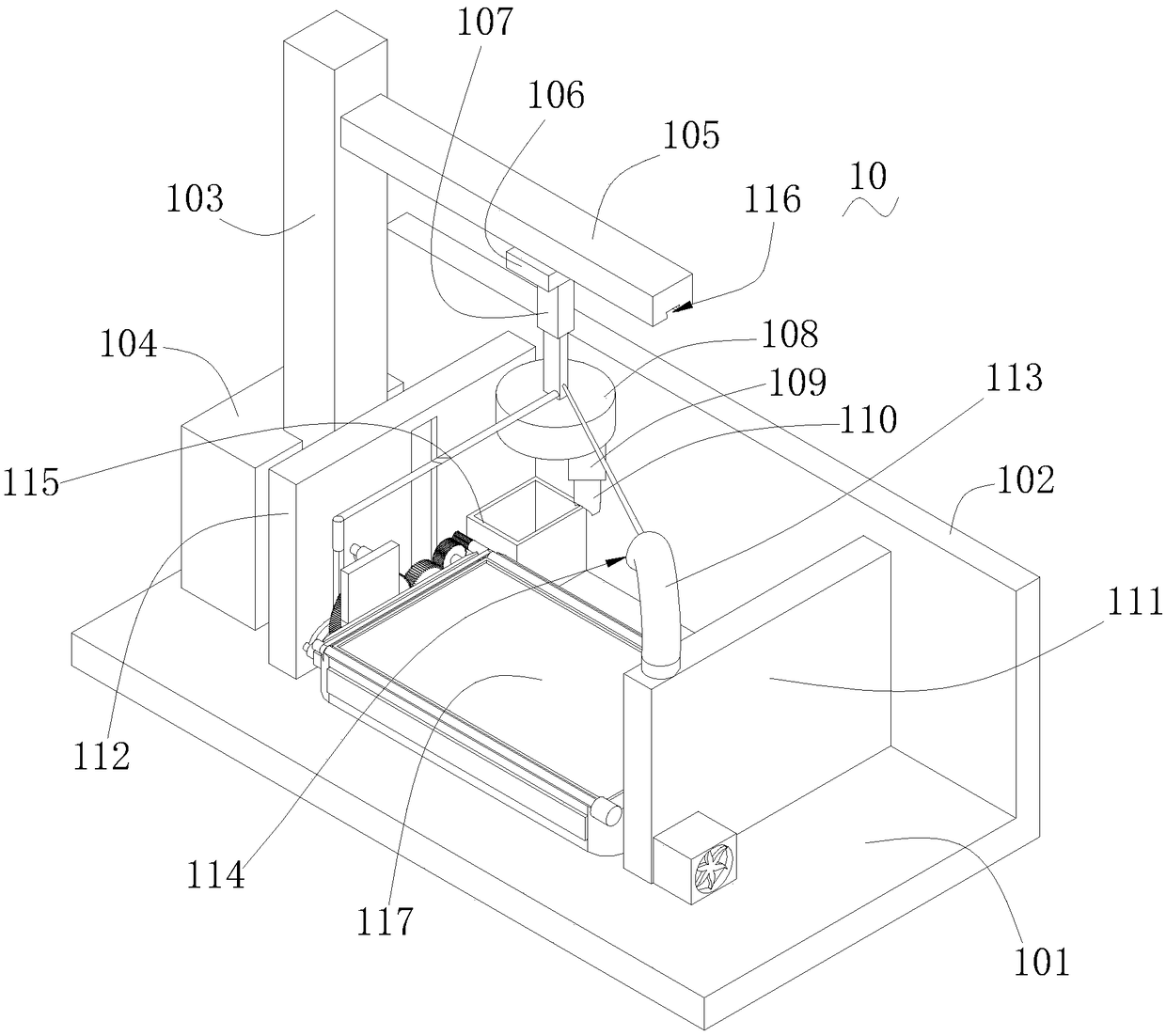
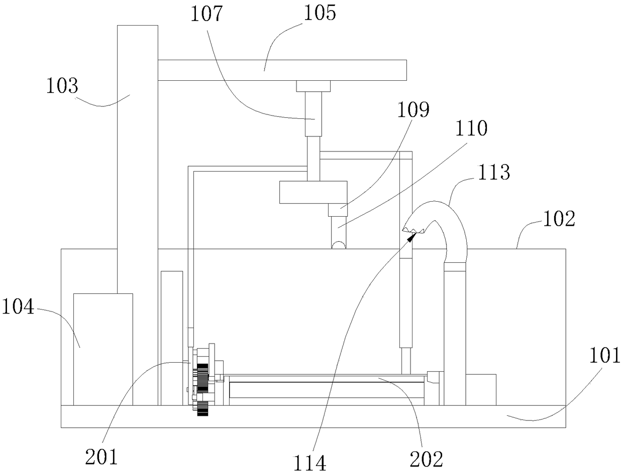
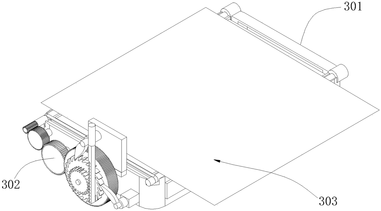
Image
Click on the blue label to locate the original text in one second.
Reading with bidirectional positioning of images and text.
Examples
Embodiment Construction
[0019] The embodiments of the present invention will be described in detail below with reference to the accompanying drawings, but the present invention can be implemented in various ways defined and covered by the claims.
[0020] see figure 1 , which is a structural schematic diagram of a cleanable clothing puncher in a preferred embodiment of the present invention. For example, a cleanable clothing puncher 10 includes a base 101, a baffle plate 102, a column 103, a control box 104, and a fixing plate 105 , slider 106, telescopic rod 107, turntable 108, motor 109, drill bit 110, first fixture support 111, second fixture support 112, support rod 113, electric fan 114, dust box 115, one part of base 101 The side is provided with a baffle 102, the upper surface of the base 101 is provided with a column 103, one side of the column 103 is provided with a control box 104, the upper end of the column 103 is fixedly connected with a fixed plate 105, and the bottom of the fixed plate...
PUM
Abstract
The invention provides a cleanable clothing material puncher which comprises a base, a baffle, a column, a control box, a fixing plate, a sliding block, a telescopic rod, a turntable, a motor, a drill bit, a first clamp support, a second clamp support, a first sliding groove, a press plate, a supporting rod, an electric fan, a dust collecting box, a garment material, a foam plate, a second sliding groove and a third sliding groove. A feeding mechanism comprises a material laying device and a material pressing device. The material laying device comprises a material laying part and a feeding device, wherein the material laying part is arranged at the bottom of a punching device. The first clamp support is provided with a supporting rod, the supporting rod is provided with the electric fan, and the second clamp support is provided with the dust collecting box. The cleanable clothing material puncher utilizes the electric fan to blow dust produced on ends or fabrics due to punching into the dust collecting box, a press block is in abutting connection wit a material to be processed when a lifting air cylinder moves down, accordingly the material to be processed is pressed on a punching foam block and is prevented from moving, accordingly holes formed by the drill bit are more exquisite, and the edges of the holes are smoother.
Description
technical field [0001] The invention relates to the technical field of cloth processing machinery, in particular to a cleanable cloth hole puncher. Background technique [0002] In the fabric cutting production process in garment manufacturing enterprises, the fabric needs to be lined, punched, cut, sewn, buttoned, quality inspected, sealed and other processes on the fabric according to the garment layout designed by the designer. listed. Among them, the punching machine needs to be used in the punching process, and the punching machine is a very widely used industrial machine, which is used in almost all industrial industries; in the textile industry, the punching machine is also a A very important textile machinery, many textile products have punching requirements, and the development of punching machines in the textile industry is also very rapid; from the perspective of the development of punching machines, it has experienced manual punching machines, mechanical punchin...
Claims
Application Information
Patent Timeline
Application Date:The date an application was filed.
Publication Date:The date a patent or application was officially published.
First Publication Date:The earliest publication date of a patent with the same application number.
Issue Date:Publication date of the patent grant document.
PCT Entry Date:The Entry date of PCT National Phase.
Estimated Expiry Date:The statutory expiry date of a patent right according to the Patent Law, and it is the longest term of protection that the patent right can achieve without the termination of the patent right due to other reasons(Term extension factor has been taken into account ).
Invalid Date:Actual expiry date is based on effective date or publication date of legal transaction data of invalid patent.