Busbar drilling device
A technology for drilling devices and busbars, which is applied in the direction of boring/drilling, drilling/drilling equipment, metal processing equipment, etc., can solve the problems of easy deviation of drilling holes and incomplete overlap, and achieve simple structure, Ease of use
- Summary
- Abstract
- Description
- Claims
- Application Information
AI Technical Summary
Problems solved by technology
Method used
Image

Examples
Embodiment 1
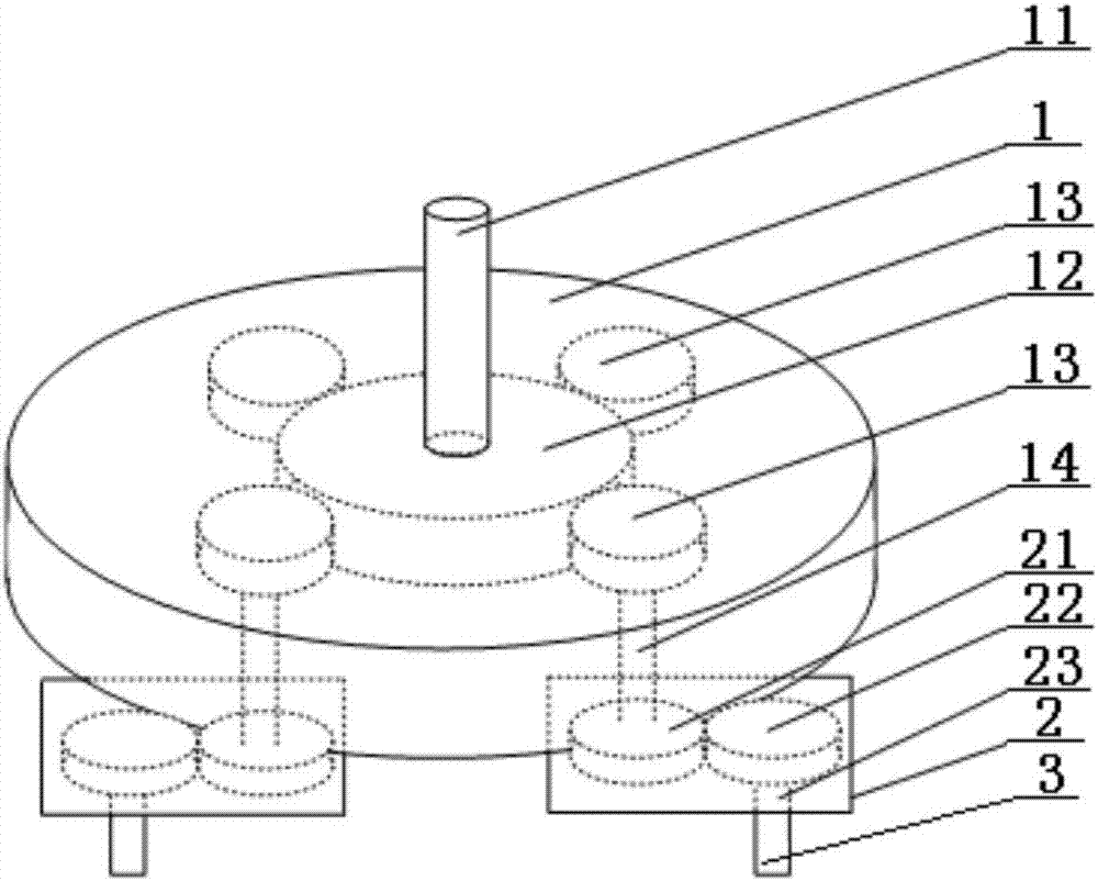
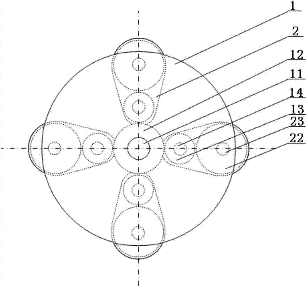
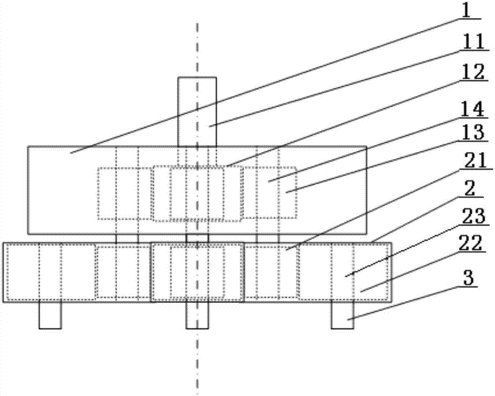
[0038] Such as Figure 1 to Figure 3 As shown, the bus bar drilling device includes: a first gear box 1, a plurality of second gear boxes 2 and drill clips 3 arranged below the first gear box 1, and a drive shaft 11, The driving gear 12 and the planetary gear 13, the driving shaft 11 is fixedly connected with the driving gear 12 and extends from the top of the first gear box 1 to the outside of the first gear box 1, there are multiple planetary gears 13 meshing with the driving gear 12, the first Two gear boxes 2 correspond to the planetary gears 13 one-to-one, and the second gear box 2 is provided with a transmission gear 21 and a working gear 22, wherein the transmission gear 21 is connected with the planetary gear 13 to realize synchronous movement, and the working gear 22 and the transmission gear 21 Engaged with each other, the drill card 3 is arranged under the second gear box 2, and is fixedly connected with the working gear 22 through the connecting shaft 23, and the b...
Embodiment 2
[0040] Such as Figure 1 to Figure 3 As shown, the bus bar drilling device includes: a first gear box 1, a plurality of second gear boxes 2 and drill clips 3 arranged below the first gear box 1, and a drive shaft 11, The driving gear 12 and the planetary gear 13, the driving shaft 11 is fixedly connected with the driving gear 12 and extends from the top of the first gear box 1 to the outside of the first gear box 1, there are multiple planetary gears 13 meshing with the driving gear 12, the first Two gear boxes 2 correspond to the planetary gears 13 one-to-one, and the second gear box 2 is provided with a transmission gear 21 and a working gear 22, wherein the transmission gear 21 is connected with the planetary gear 13 through a transmission shaft 14 to realize synchronous movement, and the working gear 22 Engaged with the transmission gear 21, the drill card 3 is arranged under the second gear box 2, and is fixedly connected with the working gear 22 through the connecting sh...
Embodiment 3
[0042] Such as Figure 1 to Figure 3 As shown, the bus bar drilling device includes: a first gear box 1, a plurality of second gear boxes 2 and drill clips 3 arranged below the first gear box 1, and a drive shaft 11, The driving gear 12 and the planetary gear 13, the driving shaft 11 is fixedly connected with the driving gear 12 and extends from the top of the first gear box 1 to the outside of the first gear box 1, there are multiple planetary gears 13 meshing with the driving gear 12, the first The second gear box 2 corresponds to the planetary gear 13 one by one, and the second gear box 2 is provided with a transmission gear 21 and a working gear 22, wherein the transmission shaft 14 runs through the first gear box 1 and the second gear box 2, and passes through the transmission The central axis of the gear 21 and the planetary gear 13, the transmission shaft can realize the synchronous movement of the transmission gear and the planetary gear, and the second gear box 2 can ...
PUM
 Abstract
Description
Claims
Application Information
 - R&D
- Intellectual Property
- Life Sciences
- Materials
- Tech Scout
- Unparalleled Data Quality
- Higher Quality Content
- 60% Fewer Hallucinations
Browse by: Latest US Patents, China's latest patents, Technical Efficacy Thesaurus, Application Domain, Technology Topic, Popular Technical Reports.
© 2025 PatSnap. All rights reserved.Legal|Privacy policy|Modern Slavery Act Transparency Statement|Sitemap|About US| Contact US: help@patsnap.com