Synthetic positioning device and method for large parts and fe ends of EMU underframe foundation

A technology for positioning devices and large parts, applied in auxiliary devices, metal processing equipment, auxiliary welding equipment, etc., can solve the problems of time-consuming, labor-intensive, poor precision, and high labor intensity in the measurement process, achieve ingenious structural design, reduce production costs, Ease of repair and maintenance

Active Publication Date: 2019-01-18
CRRC CHANGCHUN RAILWAY VEHICLES CO LTD
View PDF7 Cites 0 Cited by
  • Summary
  • Abstract
  • Description
  • Claims
  • Application Information

AI Technical Summary

Problems solved by technology

[0017] In order to solve the cumbersome process steps of the existing EMU underframe synthesis method, the staff need to repeatedly perform long-distance size measurement for the positioning of the FE end at the assembly welding station tens of meters long. The measurement process is time-consuming, laborious, and has poor accuracy. The production efficiency is low. Due to the butt weld between the edge beam and the floor in the form of lap joint, the FE end will not be able to be plugged and mated with the two edge beams from the opening end of the inner curved section of the two edge beams, resulting in The automatic welding technology cannot be directly implemented, and the welding seam of tens of meters must be completed by manual welding, resulting in the technical problems of low welding seam strength, high labor intensity, and low production efficiency. The invention provides an EMU underframe foundation Synthetic positioning device and method for large parts and FE ends

Method used


Image

  • Synthetic positioning device and method for large parts and fe ends of EMU underframe foundation
  • Synthetic positioning device and method for large parts and fe ends of EMU underframe foundation
  • Synthetic positioning device and method for large parts and fe ends of EMU underframe foundation

Examples


Embodiment Construction

[0064] The present invention will be further described in detail below in conjunction with the accompanying drawings.

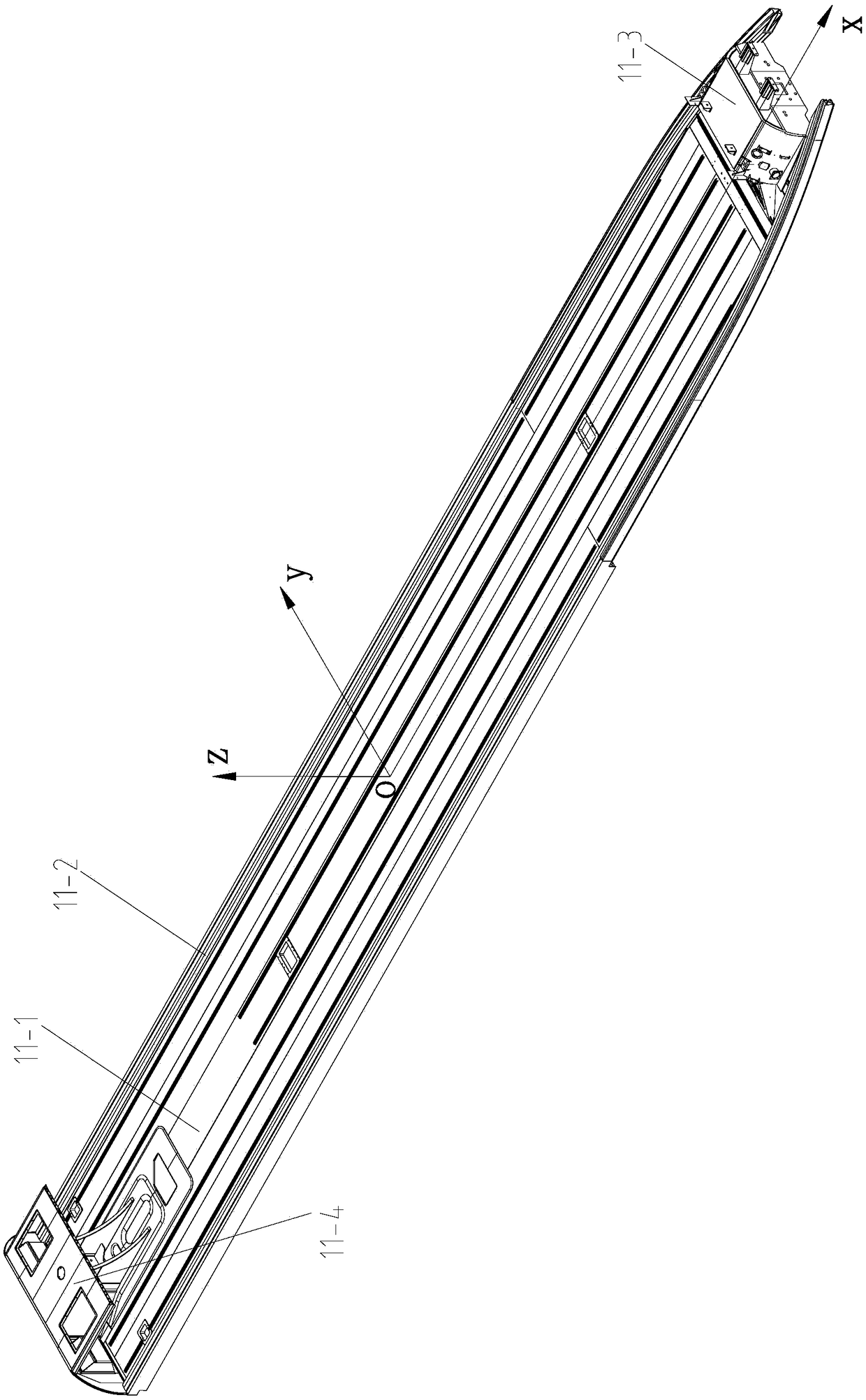
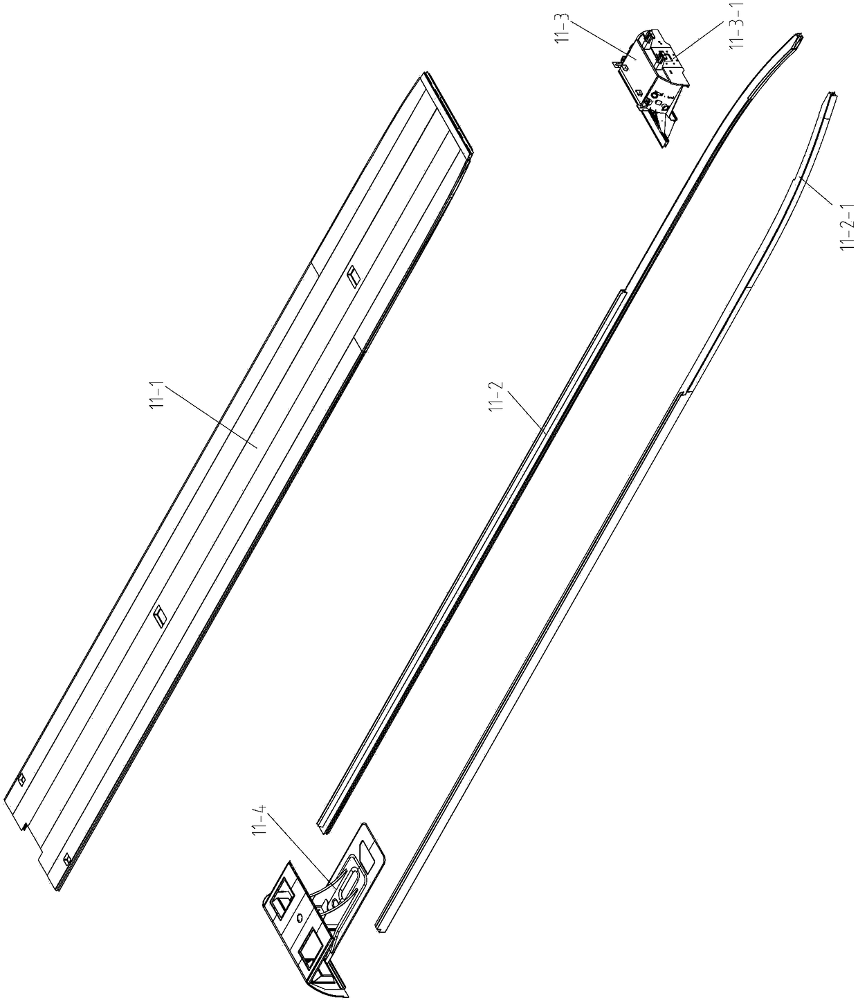
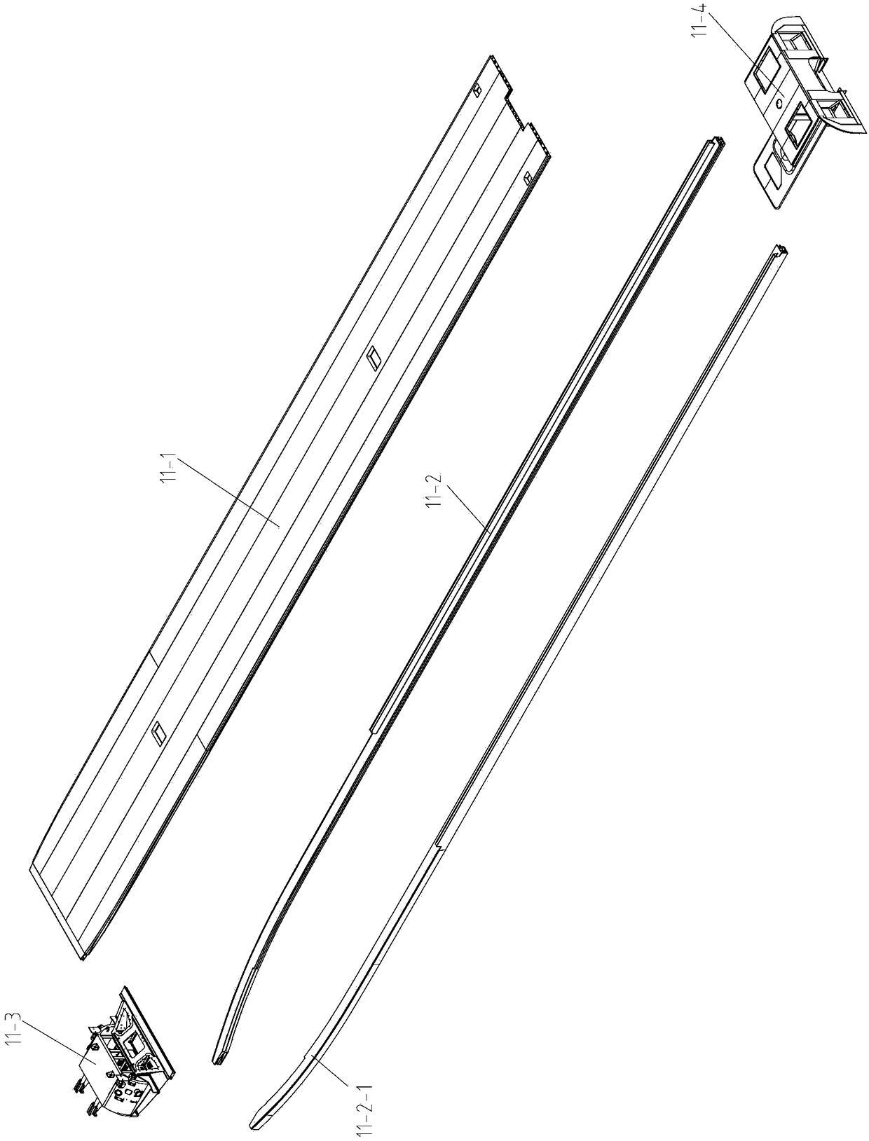
[0065] like Figure 9As shown, the composite positioning device of the base large part of the EMU underframe and the FE end of the present invention includes the FE end positioning tool, the bottom frame centerline positioning tool 1 and a plurality of side beam middle side pressing mechanisms 2, and the FE end positioning tool is used for Clamping and positioning the FE end 11-3 of the base frame 11, the base frame centerline positioning tool 1 is used to locate the center line of the base frame 11 in the length direction and the center of the base frame, and the multiple side beam middle side pressing mechanisms 2 are used for Positioning the middle of the side beam 11-2 of the base frame 11; the base frame centerline positioning tool 1 includes four positioning bases, and the four positioning bases are sequentially provided with a positioning point A, a po...


PUM


Abstract

The invention provides a composite positioning device and method for a chassis foundation large-size component and an FE end of multiple units, and belongs to the field of assembly welding positioning auxiliary devices and application methods for chassis foundation large-size components and FE end components of multiple units. The composite positioning device comprises an FE end positioning tool, a chassis center line positioning tool and multiple boundary beam middle lateral tightening mechanisms, wherein the FE end positioning tool is used for clamping and positioning an FE end of a chassis, the chassis center line positioning tool is used for positioning a center line of the chassis in the length direction and the center of the chassis, and the boundary beam middle lateral tightening mechanisms are used for positioning the middles of boundary beams of the chassis. The FE end positioning tool of the composite positioning device can be modularly produced in batches, overhauling and maintenance are facilitated, production cost is reduced, the composite positioning device becomes a basis component of assembly line work, and a new subsequent process method of integrated machining after chassis assembly welding can become possible. The subsequent new method can effectively guarantee chassis geometric sizes and is beneficial to improving the product manufacturing precision and forming quality.

Description

technical field [0001] The invention belongs to the field of auxiliary welding positioning aids for the assembly of the large basic parts of the underframe and the FE end parts of the EMU and its use method, and in particular relates to a combined positioning device and method for the large basic basic parts of the EMU underframe and the FE end. Background technique [0002] like Figure 1 to Figure 4 As shown in the figure, the underframe 11 of the head car of the existing Chinese standardized EMU train is an integral welded large component with a length of several tens of meters. The underframe 11 includes a floor 11-1, two side beams 11-2, FE (underframe front end; front end of the chassis) end 11-3 and end chassis 11-4, the two side beams 11-2 are symmetrical with each other, and their front ends are provided with side beam inner curved arc segments 11-2-1. [0003] like Image 6 a and Image 6 As shown in b, the end chassis 11-4 includes a long end chassis cover plate...

Claims


Application Information

Patent Timeline
Patent Type & Authority Patents(China)
IPC IPC(8): B23K37/04B23K37/00
CPCB23K37/00B23K37/0443
Inventor 王世君王永亮李香子
Owner CRRC CHANGCHUN RAILWAY VEHICLES CO LTD
Why Eureka
Try Eureka