Cooling crucible for vacuum electron beam smelting

A technology of vacuum electron beam and cold crucible, which is applied in the direction of crucible furnace, furnace cooling, furnace components, etc., can solve the problems of high processing cost and affect the reliability of the evaporation system, reduce processing cost, ensure water cooling effect and uniformity, Effect of increased cooling area

Active Publication Date: 2017-11-17
RES INST OF PHYSICAL & CHEM ENG OF NUCLEAR IND +1
View PDF9 Cites 6 Cited by
  • Summary
  • Abstract
  • Description
  • Claims
  • Application Information

AI Technical Summary

Problems solved by technology

[0004] Although the above structure overcomes the temperature of local evaporation, the formation of the entire waterway needs to be realized by vacuum brazing, which has high processing costs, is limited by the heat load, and has potential safety hazards of water leakage, which affects the reliability of the evaporation system.

Method used


Image

  • Cooling crucible for vacuum electron beam smelting
  • Cooling crucible for vacuum electron beam smelting
  • Cooling crucible for vacuum electron beam smelting

Examples


no. 2 Embodiment

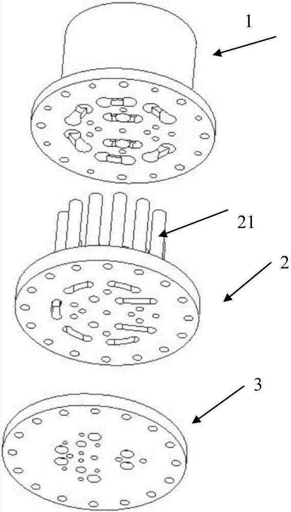
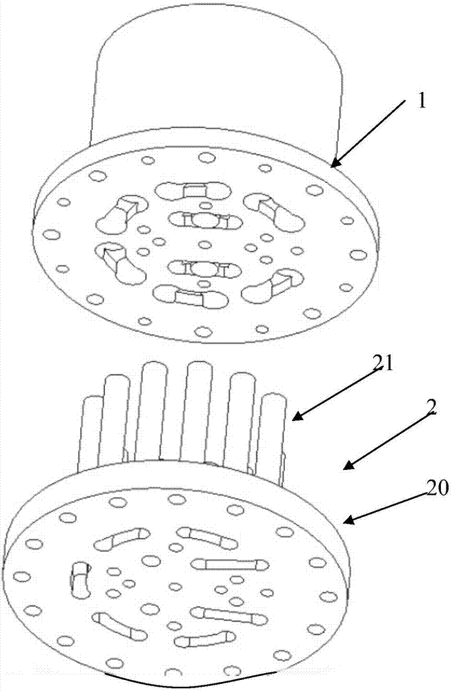
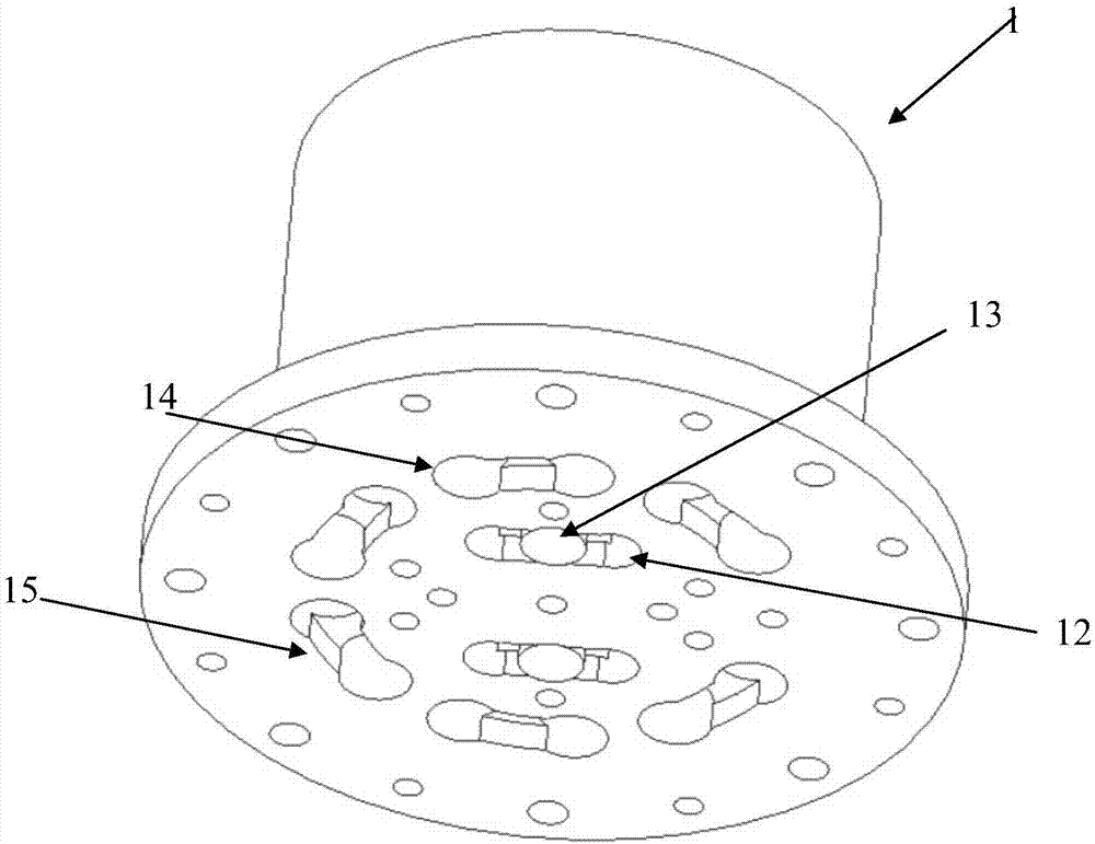
[0047] In order to realize the overall flow path design, the n is an odd number, the water tank is a section of C-shaped water tank, a water guide pipe is connected with the water inlet pipe, one end of the water tank is connected with the water outlet pipe, and a water hole is connected with the other end of the water tank It is connected by connecting parts, and the number of said connecting parts is (n-1) / 2, so as to connect the water guide pipes of the corresponding group. The layout of the C-shaped water tank makes the bottom of the material pool also have more evenly distributed cooling points to achieve bottom temperature control. The flow path of the water-cooling mechanism at the bottom of the material pool is connected in series with the flow path of the water-cooling mechanism around the material pool, and different structural parameter designs are adopted for different parts, so that temperature control can also be realized. Of course, in this embodiment, it is also...

no. 3 example

[0049] The n is an even number, the water tank is a section of C-shaped water tank, the two ends of the water tank are respectively connected with a group of water holes through the connecting part, and the two connecting parts and the water tank constitute the group of water holes. For the connecting groove of the hole, the number of connecting parts is n / 2-1 to connect the corresponding group of aqueducts, and the remaining two aqueducts are respectively connected to the water inlet pipe and the water outlet pipe. The difference between this embodiment and the second embodiment is that the flow path of the water-cooling mechanism at the bottom of the material pool is connected in series to the middle of the flow path of the water-cooling mechanism around the material pool. The rest of the structure is similar to the first embodiment and will not be expanded here. describe.

[0050] Of course, as a further modification of this embodiment, the two ends or one end of the water ...


PUM


Abstract

The invention discloses a cooling crucible for vacuum electron beam smelting. The cooling crucible comprises a crucible body with a material pool being formed in the top center, and a base fixedly connected with the bottom of the crucible body. According to the water cooling crucible, different flow channel design modes are adopted for different positions, the pertinence is high, the water cooling effect and uniformity of the water cooling pipe crucible can be effectively ensured, meanwhile, no weld joint is formed in the crucible body through the two flow channel designs, the potential risk of water leakage is avoided, the equipment reliability is improved, and the machining cost is lowered; and through the mode of drilling water holes and embedding water guiding pipes in the water holes and sleeve internal and external circulation, a circulation water channel is formed jointly, the machining precision can be ensured, the water channel cooling area can be adjusted flexibly by adjusting the hole diameter, the water hole position and the water tank width, thus, the cooling area is increased, and different heating load requirements are met.

Description

technical field [0001] The invention relates to a crucible, in particular to a cold crucible for vacuum electron beam melting. Background technique [0002] Vacuum metal smelting and purification technology. In the evaporation system, a water-cooled welded copper crucible is used as the carrier of the evaporation heat source. Copper has very good thermal conductivity. Under water-cooling conditions, it can well reduce its own temperature and ensure performance. The existing cooling water channel generally adopts the water channel structure of bottom-in and top-out. [0003] Chinese patent CN 204987858U discloses a water-cooled crucible for an electron beam melting furnace, which includes a base, the upper end of the base forms a convex ring, the outer water jacket and the lower end of the jacket are connected to the top surface of the convex ring, and the lower end of the inner water jacket is inserted into the convex ring. And connected with the base, the outer water jacke...

Claims


Application Information

Patent Timeline
Patent Type & Authority Applications(China)
IPC IPC(8): F27B14/10F27D9/00
CPCF27B14/10F27D9/00F27D2009/0013F27B2014/108F27M2003/13Y02P10/25
Inventor 许文强慈连鳌赵国华高学林罗立平张晓卫
Owner RES INST OF PHYSICAL & CHEM ENG OF NUCLEAR IND
Why Eureka
Try Eureka