
Design and manufacturing of drop hammer type impact clamp capable of adjusting and controlling impact position points in plane

A technology of impact position and drop hammer type, which is applied in the direction of measuring devices, instruments, scientific instruments, etc., can solve the problems of quantitative control of impact position points, and the impact performance of materials cannot be fully and truly tested and characterized, so as to reduce irrelevant variables and improve The effect of trial efficiency

Active Publication Date: 2017-11-17
TIANJIN POLYTECHNIC UNIV
View PDF10 Cites 16 Cited by
  • Summary
  • Abstract
  • Description
  • Claims
  • Application Information

AI Technical Summary

Problems solved by technology

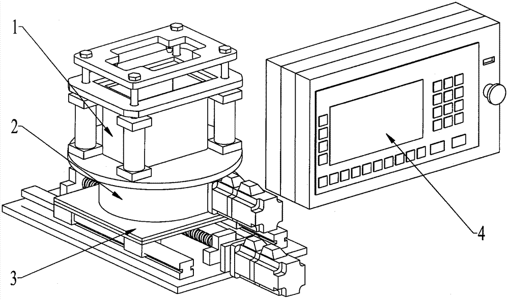
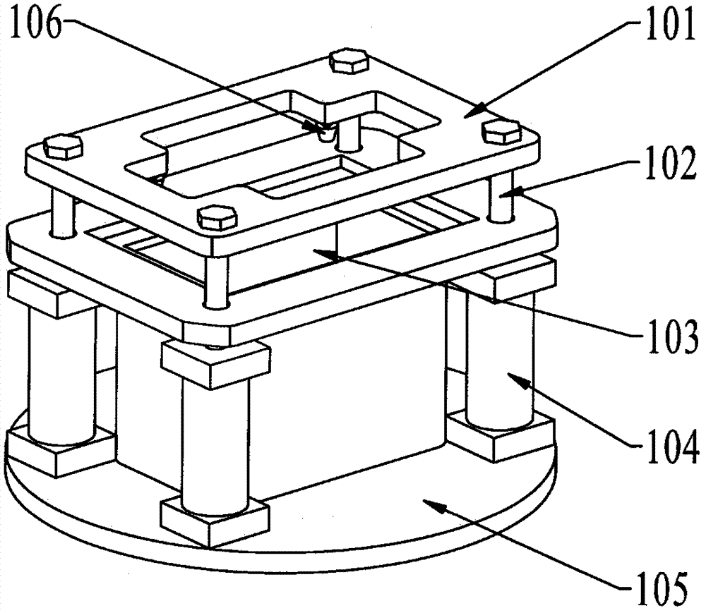
[0006] Aiming at the problem that the impact position of the existing impact fixture cannot be continuously and precisely controlled quantitatively in the one-dimensional, especially two-dimensional plane area, and the impact performance of the material cannot be fully and truly tested and characterized, the present invention provides a new type of single-use It is a mobile platform that coordinates displacement and fixed axis rotation to realize the adjustment of the plane position point. The programmable logic controller (PLC) is used to control the servo motor to drive the ball screw of the one-way mobile platform to rotate to realize the horizontal line displacement regulation and the fixed axis rotation platform worm gear or cone. High-precision angular displacement control of gears or cross-axis helical gears, the two cooperate to complete the high-precision continuous quantitative adjustment of the impact position point of the rectangular test plate in the impactable area

Method used


Image

  • Design and manufacturing of drop hammer type impact clamp capable of adjusting and controlling impact position points in plane
  • Design and manufacturing of drop hammer type impact clamp capable of adjusting and controlling impact position points in plane
  • Design and manufacturing of drop hammer type impact clamp capable of adjusting and controlling impact position points in plane

Examples


Embodiment 1

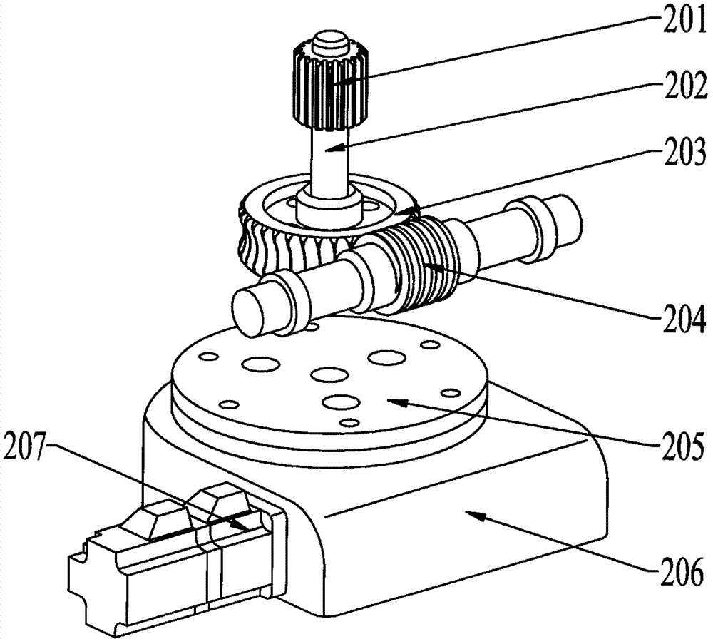
[0051] In this embodiment, a space gear mechanism and a worm gear are selected as the transmission mechanism of the fixed-axis rotating platform. The worm gear mechanism can be regarded as an evolution of the cross-axis helical gear mechanism. The worm and gear mechanism is in line contact, with stable transmission and low noise. When the lead angle is small, the worm gear mechanism is self-locking, that is, it cannot drive when the turbine is active. The worm gear should be made of wear-resistant material. Like the crossed-axis helical gear mechanism, the worm gear mechanism not only slides along the tooth height direction, but also has a large sliding speed along the tooth direction, which is easy to cause heat and wear. Therefore, the worm gear should be made of expensive anti-friction and wear-resistant materials such as copper alloy, and it also needs good lubrication and heat dissipation conditions.

[0052] Such as image 3Shown is a schematic diagram of a fixed-axi...

Embodiment 2

[0054] In this embodiment, the bevel gear of the space gear mechanism is selected as the transmission mechanism of the fixed-axis rotating platform. The bevel gear mechanism is used to transmit motion and power between the intersecting shafts, and the angle Σ between the two shafts can be determined according to needs, and Σ is 90° in the present invention. Bevel gears are divided into straight teeth and curved teeth. Curved bevel gears have stable transmission and large load capacity, and are used in automobiles and tractors. Straight bevel gears are widely used because they are relatively simple to design and manufacture. What selected in this embodiment is a straight bevel gear.

[0055] Such as Figure 10 Shown is a schematic diagram of a fixed-axis rotating platform with a straight-toothed bevel gear mechanism as the transmission mechanism, which consists of a center wheel 201, a transmission shaft 202, a horizontal straight-toothed bevel gear 210, a vertical straight-...

Embodiment 3

[0057] In this embodiment, a space gear mechanism with crossed-axis helical gears is selected as the transmission mechanism of the fixed-axis rotating platform. Cross-axis helical gear transmission is also called helical gear transmission. As far as its single gear is concerned, it is a helical gear. It is different from external meshing parallel shaft helical gear transmission. The helix angle of the two wheels is not necessarily equal, and the direction of rotation is not necessarily the same. on the contrary. Therefore, after installation, it becomes a transmission between space interlaced shafts. Compared with spur gears, helical gears generate less shock and vibration, and the meshing stability is much better than that of spur gears. Due to the large coincidence degree of the helical gear, the total length of the contact line is large, and the load-carrying capacity of the gear is high. Helical gears have a smaller minimum number of teeth than spur gears, so fewer gears...


PUM

PropertyMeasurementUnit
lengthaaaaaaaaaa
widthaaaaaaaaaa
depthaaaaaaaaaa

Abstract

The invention discloses a design and manufacturing of a drop hammer type impact clamp capable of adjusting and controlling impact position points in a plane, relates to the fields of testing and evaluation of impact properties of metals, non-metals and composite materials and particularly relates to a drop hammer type impact testing machine clamp capable of rapidly and accurately positioning the impact position points in an impactable plane by virtue of a creative two-dimensional movement platform. The impact position points cannot be continuously adjusted and controlled in the impactable plane, and impact performance test and evaluation of materials at a non-fixed point under actual service conditions cannot be realized by virtue of an existing drop hammer type impact testing machine. Aiming at the problems, a fixed shaft rotating platform and a one-way movement platform are controlled by virtue of a programmable controller and are matched to form a novel movement platform, and any impact point in the plane can be accurately adjusted, so that the movement problem of the impact position points in an extremely small mounting space of the impact testing machine is solved, and the testing of the repeated impact property of the non-fixed point in the plane of an impact sample is realized.

Description

technical field [0001] The invention relates to the field of impact performance testing and evaluation of metals, non-metals and composite materials, and in particular to a plate-shaped drop hammer impact testing machine that uses an innovative two-dimensional mobile platform to quickly and accurately locate the impact point within the impactable plane area. Specimen fixture. The innovative two-dimensional mobile platform is composed of a one-way mobile platform and a fixed-axis rotating platform. The quantitative rotation of two servo motors is controlled by a programmable logic controller (Programmable Logic Controller), which can realize high-precision regulation and control of the one-way displacement of the mobile platform. The high-precision control of the angular displacement of the worm gear or bevel gear or the cross-axis helical gear in the fixed-axis rotating platform, the linkage and cooperation of the two platforms realize the continuous quantitative adjustment of...

Claims


Application Information

Patent Timeline
Patent Type & Authority Applications(China)
IPC IPC(8): G01N3/303G01N3/04
CPCG01N3/04G01N3/303G01N2203/0039G01N2203/0411
Inventor 张国利王志鹏马欢王伟伟陈光伟
Owner TIANJIN POLYTECHNIC UNIV
Learn More