
A fast scanning detection method

A detection method and fast scanning technology, which is applied in the field of optical ranging, can solve the problems of continuous rapid detection distance, etc., and achieve the effect of continuous rapid rotating scanning detection, eliminating motion blur, and reducing the time of ranging

Active Publication Date: 2020-07-28
BENEWAKE BEIJING TECH CO LTD
View PDF7 Cites 0 Cited by
  • Summary
  • Abstract
  • Description
  • Claims
  • Application Information

AI Technical Summary

Problems solved by technology

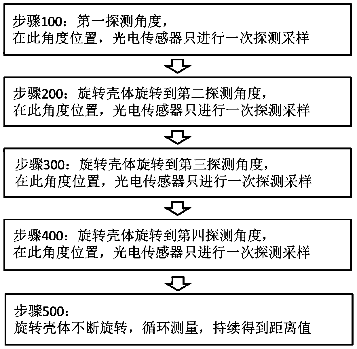
[0006] In order to solve the problem of obtaining a distance value of the detection device in the prior art, it is necessary to perform multiple data sampling on the same detection area, and the problem that the rapid detection distance cannot be sustained, this application provides a fast scanning detection method

Method used


Image

  • A fast scanning detection method
  • A fast scanning detection method
  • A fast scanning detection method

Examples


Embodiment Construction

[0022] In order to enable those skilled in the art to better understand the solution of the present application, the technical solution in the embodiment of the application will be clearly and completely described below in conjunction with the accompanying drawings in the embodiment of the application. Obviously, the described embodiment is only It is an embodiment of a part of the application, but not all of the embodiments. Based on the embodiments in this application, all other embodiments obtained by persons of ordinary skill in the art without creative efforts shall fall within the scope of protection of this application.

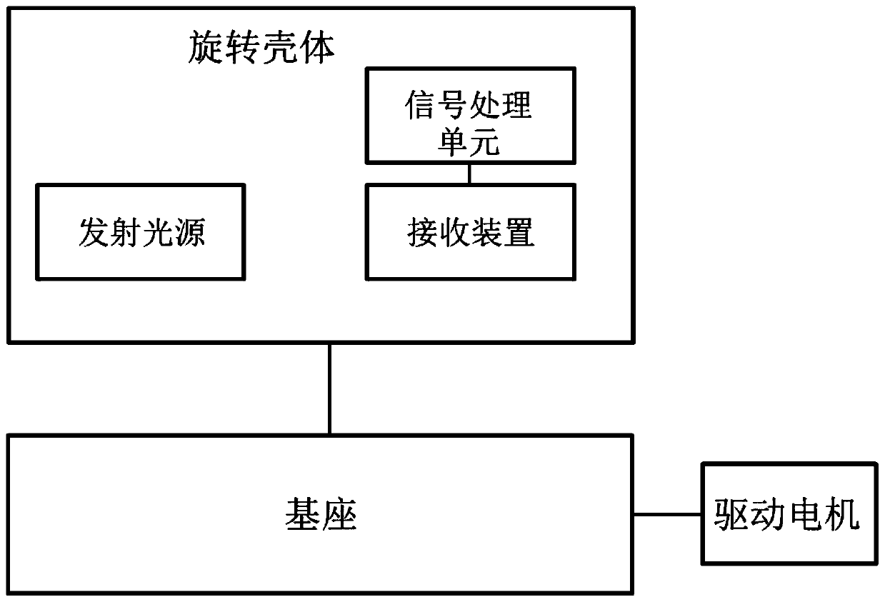
[0023] The present application relates to a fast scanning detection method. During the distance detection process, the rotating housing of the scanning detection device continuously rotates relative to the base to realize fast scanning within a range of 360 degrees to obtain distance information. The fast scanning detection method involved in the prese...


PUM


Abstract

The present application relates to a fast scanning detection method, which is used for a rotating scanning detection device that requires two or more detection samplings for the calculation of each scanning detection distance value, wherein each detection sampling includes: an emission light source emits an infrared Detection light; infrared detection light propagates in space, and is reflected when it encounters the measured object; the photoelectric sensor in the receiving device receives the infrared detection light reflected by the measured object; the rotating scanning detection device is at each detection angle position, only one probe sample is taken. A fast scanning detection method involved in this application, since only one detection sampling is required at each detection angle of the rotary scanning detection device, the time for the rotary scanning detection device to stay at each detection angle is reduced, and the rotation scanning The detection device rotates continuously and rapidly, so as to realize the detection of continuous rapid rotation scanning.

Description

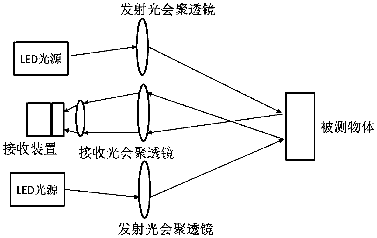
technical field [0001] The present application relates to the field of optical ranging, in particular, to a fast scanning detection method. Background technique [0002] The optical rotary scanning detection device is a device that uses collimated beams to perform non-contact scanning detection through triangulation, time of flight (Time of Flight, referred to as TOF) and other methods. At present, a common time-of-flight optical rotary scanning detection device includes: a light emitting module, an optical lens, a chip for receiving and processing signals, a motor, a bearing and a conductive slip ring. The light emitting module emits a detection beam. The optical lens is located on the optical path of the light emitting module. The collimated light beam is emitted to the surface of the object to be measured. After encountering an obstacle, the light beam is reflected to the receiving chip, and the receiving chip transmits it to the receiving point through measurement. The ...

Claims


Application Information

Patent Timeline
Patent Type & Authority Patents(China)
IPC IPC(8): G01S17/10G01S17/89
CPCG01S17/10G01S17/42G01S7/4813G01S7/4817G01S17/89G01S17/08
Inventor 郑凯王瑞李远
Owner BENEWAKE BEIJING TECH CO LTD
Learn More