
Control moment gyroscope, control moment gyroscopic instrument and mobile device

A technology for controlling moment gyroscopes and gyroscope discs, applied in the direction of non-electric variable control, control/regulation system, torque/mechanical power control, etc., which can solve the problem of consumption, inability to effectively correct the operating state of the flight process, and large energy consumption, etc. question

Active Publication Date: 2017-11-17
ZHUHAI PANLEI INTELLIGENT TECH CO LTD
View PDF8 Cites 2 Cited by
  • Summary
  • Abstract
  • Description
  • Claims
  • Application Information

AI Technical Summary

Problems solved by technology

The electronic gyroscope is low in cost, has no rotating parts and is light in weight, but it cannot meet the different needs of different flight conditions. In case of strong wind, direction change, turbulence, electromagnetic interference and other different situations, it may lose its function and the aircraft will be separated from the aircraft. The original flight track even dumped
In addition, the electronic gyroscope is easily interfered by the electromagnetic environment, and the use occasions are often limited, and the electronic gyroscope generally adopts the control method of post-release. When encountering sudden flight conditions, due to the lag of the control, the flight cannot be effectively corrected. The operating state in the process; secondly, the electronic gyroscope is to control the whole machine, so that the overall restoration of the aircraft to a stable state requires a large amount of energy consumption

Method used


Image

  • Control moment gyroscope, control moment gyroscopic instrument and mobile device
  • Control moment gyroscope, control moment gyroscopic instrument and mobile device
  • Control moment gyroscope, control moment gyroscopic instrument and mobile device

Examples


no. 1 example

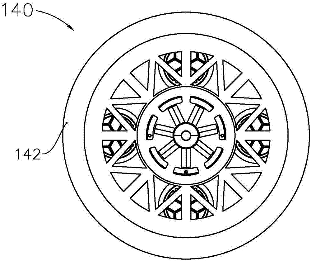
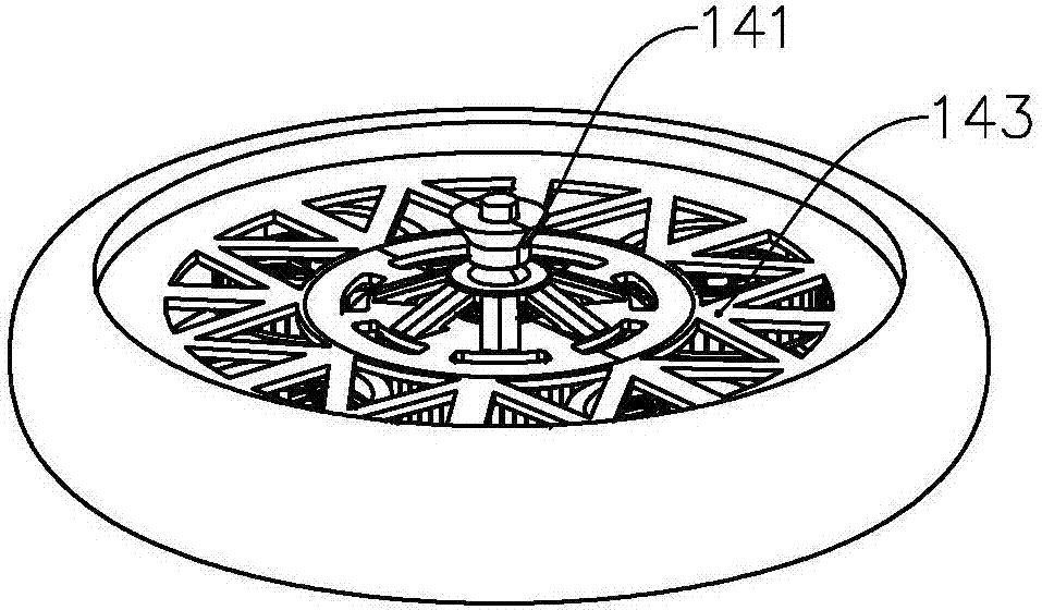
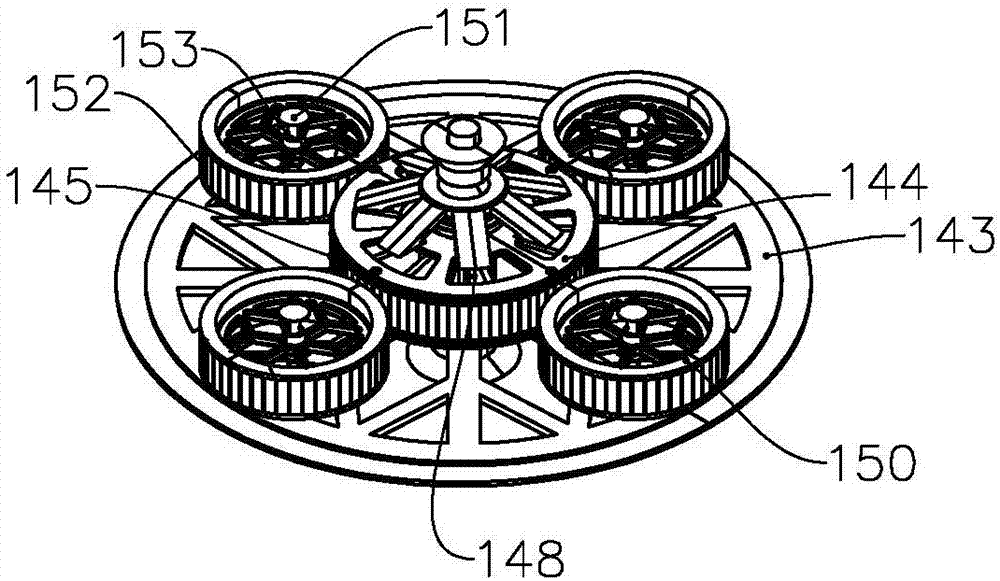
[0050] like figure 1 , figure 2 , image 3 As shown, the control torque gyroscope 140 includes a driving device (not shown) and a gyro disk, and the driving device drives the gyro disk to rotate along its rotation axis 141 . The driving device includes a rotor 148 and a fixed base 144, the rotor 148 is arranged coaxially with the main disc body 147 and is relatively fixed, and the rotor 148 can rotate relative to the fixed base 144; Auxiliary disk body 150, the auxiliary disk body 150 is distributed along the circumferential direction of the gyro disk, and can rotate around its rotation axis 151, the rotation axis 151 intersects with the normal plane of the rotation axis 141, and the direction of the angular velocity component of the auxiliary disk body in the rotation axis 141 direction It is consistent with the direction of the angular velocity of the main disc body 147 . The main disc body 147 also includes two discs 143 and an annular hoop 142, the rotating shaft 141 i...

no. 3 example

[0064] like Figure 7 , Figure 8 , Figure 9 As shown, the control moment gyroscope 10 includes a gyroscope disc 1 , a gyroscope disc side wall 2 , an auxiliary disc body 3 , a driving device 4 , a rotating shaft 5 , and a one-way bearing 8 . The gyro disk 1 includes an upper disk body 11 and a lower disk body 12; the auxiliary disk body 3 includes a second annular magnetic pole array 31, an auxiliary disk body bearing 32, an auxiliary disk body rotation axis 33, and an auxiliary disk body disk body 34; the driving device 4 includes a first annular magnetic pole array 41, a rotor 42, a coil stator 43, and a fixing seat 44.

[0065] The upper disc body 11 and the lower disc body 12 of the gyro disc 1 are assembled and combined, the side wall 2 of the gyro disc is clamped and assembled by the upper disc body 11 and the lower disc body 12, and the rotating shaft 5 is connected with the upper disc body 11 and the lower disc body of the gyro disc 1 The body 12 is connected, whe...


PUM


Abstract

The invention discloses a control moment gyroscope, a control moment gyroscopic instrument with the control moment gyroscope and a mobile device having the control moment gyroscopic instrument. The control moment gyroscope provided by the invention comprises a driving device and a gyroscope disc. The driving device drives the gyroscope disc to rotate along the rotation axis of the gyroscope disc. The gyroscope disc includes a main disc body and at least two sub disc bodies disposed on the main body. The sub disc bodies are uniformly distributed along the circumference of the gyroscope disc and rotate around the auto rotation axis, the auto rotation axis intersects a normal plane of the rotation axis, and the direction of angular velocity components of the sub disc bodies in the direction of the rotation axis coincides with the direction of the angular velocity of the main disc body. The advantages of compact overall size of the gyroscope disc, small volume and large moment of momentum are gained.

Description

technical field [0001] The invention relates to a control moment gyroscope, especially a control moment gyroscope with small volume and large momentum moment, a control moment gyroscope with the control moment gyroscope and a traveling device with the control moment gyroscope. Background technique [0002] A rigid body that rotates at a high speed around a fulcrum is called a gyroscope. The so-called gyroscope generally refers to a symmetrical gyroscope, which is a rigid body with uniform mass distribution and symmetrical structure, and the axis of symmetry is its axis of rotation. Gyro devices with various functions made by people using the mechanical properties of gyroscopes are called gyroscopes. [0003] The axis fixation of the gyroscope is directly proportional to the moment of inertia and the angular velocity of the gyroscope. Therefore, the gyroscope with a strong axis fixation is generally large in size, resulting in a bulky structure and a long start-up time. Whe...

Claims


Application Information

Patent Timeline
IPC IPC(8): G05D17/02
CPCG05D17/02
Inventor 何春旺
Owner ZHUHAI PANLEI INTELLIGENT TECH CO LTD
Learn More