
Bridge anti-collision early warning system and method

An early warning system and bridge technology, applied in traffic control systems, ships, instruments, etc., can solve the problems of narrow waters, hindering navigation safety, and inability to adapt to bridge areas, saving working time and reducing maintenance costs.

Active Publication Date: 2017-11-17
祖小鸿
View PDF7 Cites 10 Cited by
  • Summary
  • Abstract
  • Description
  • Claims
  • Application Information

AI Technical Summary

Problems solved by technology

Traditional buoys are divided into two types: one is set on the bank of the river, called the shore mark, according to the ship navigation regulations, the waters where the shore mark is set, and the central waters of the river 30 meters away from the shore are the navigation waters; obviously this This type of shore marker cannot be adapted to the bridge area
The other is set in the river waters, called buoys, this kind of buoy is carried by a tiny buoy boat. Although the buoy boat can float on the water, it is fixed by cables and anchors. When the water level rises or When landing, the position of the navigation mark will change. In order to guide accurately, the maintenance personnel must readjust the cable or even re-anchor. If this kind of buoy is set at the pier, the water area at the pier is narrow, and the passing ships are very busy. Maintenance personnel often To adjust will hinder the safety of navigation, and will also increase the working hours of maintenance personnel

Method used


Image

  • Bridge anti-collision early warning system and method
  • Bridge anti-collision early warning system and method
  • Bridge anti-collision early warning system and method

Examples


Embodiment Construction

[0031] The present invention will be described in detail below in conjunction with the accompanying drawings.

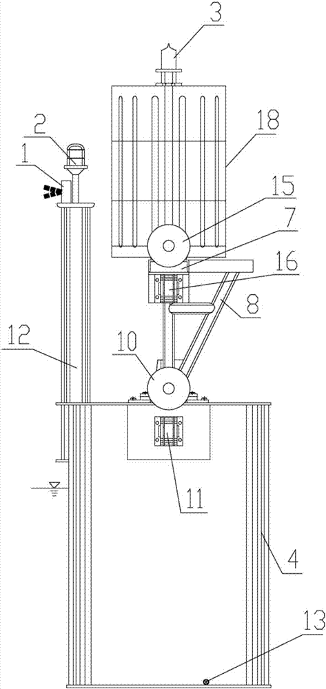
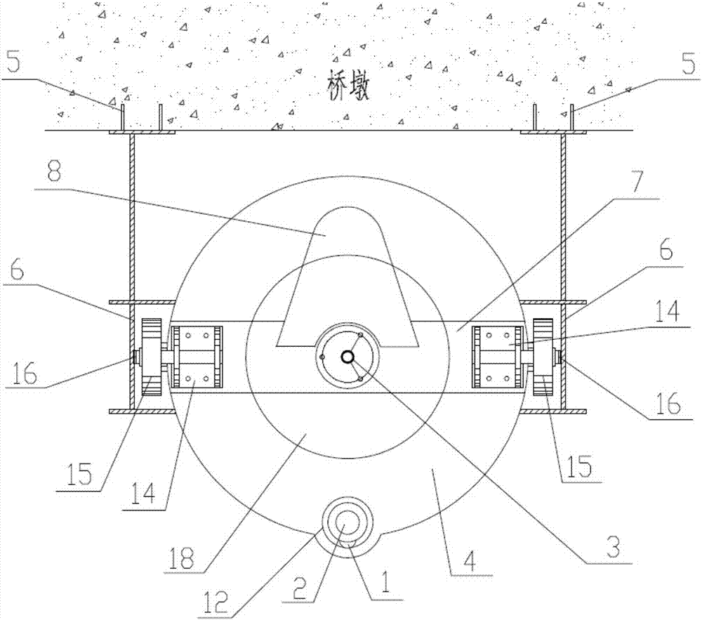
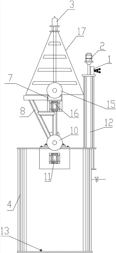
[0032]Take a bridge with one navigable opening and two piers as an example. Such as Figures 1 to 5 As shown, the bridge anti-collision early warning system includes the control center and four early warning devices installed on the piers on both sides of the bridge navigation hole; among them, one is installed on the upper and lower reaches of the left pier such as image 3 The early warning device shown in the figure is used to give early warning to the left pier, and one is installed on the upstream and downstream of the right pier, such as figure 1 The early warning device shown is for early warning of the right pier, and the four early warning devices work independently without interfering with each other.

[0033] Such as figure 1 , figure 2 , Figure 4 The shown early warning device includes a radar detector 1, an audible and visual alarm 2, a navigation...


PUM


Abstract

The invention discloses a bridge anti-collision early warning system and method. The system comprises a control center and a plurality of early warning apparatuses, each early warning apparatus comprises a radar detector, an audible-visual alarm, a navigation mark, a navigation mark lamp, a closed buoy, buoy elevation guiding limiting assemblies, anchor bars, and guide rails, the radar detector comprises a radar, a control module and a wireless communication module, the radar and the audible-visual alarm are electrically connected with the control module, the control module is electrically connected with the wireless communication module, the wireless communication module communicates with the control center in a wireless manner, the radar detector, the audible-visual alarm, and the navigation mark are arranged on the buoy, the buoy can move up and down relative to the guide rails under the buoyancy effect of water through the buoy elevation guiding limiting assemblies, and whether an alarm is given and / or whether intrusion ships are notified are / is determined according to the time and area of the ships intruding into a radar monitoring defense area. According to the system and method, the ships can be accurately guided, the alarm is given when the navigation of the ship deviates, and the ships can be prevented from colliding with the bridge.

Description

technical field [0001] The invention belongs to the field of water ship traffic safety facilities, and in particular relates to a bridge anti-collision early warning system and method. Background technique [0002] The current bridge anti-collision measures mainly adopt passive anti-collision methods, that is, adopt floating enclosures, cable interception, pile protection, artificial islands, pile groups, cofferdams, semi-cofferdams, composite steel floating enclosures, etc., in an effort to improve the pier's ability to withstand ship collisions. Although the passive anti-collision method can reduce the damage to bridge piers caused by collision accidents to a certain extent, the cost of passive anti-collision facilities is high, the maintenance cost is high, and it can only protect bridges but not ships. Aiming at the deficiencies of passive anti-collision methods, people have carried out bridge anti-collision warning device research: such as a bridge anti-collision system...

Claims


Application Information

Patent Timeline
IPC IPC(8): G08G3/02B63B35/00B63B51/00
CPCB63B35/00B63B51/00G08G3/02
Inventor 祖小鸿
Owner 祖小鸿
Learn More